
ESP32 and L298N Motor Driver Controlled Robot with Ultrasonic Sensor
View and Edit Project In Cirkit Designer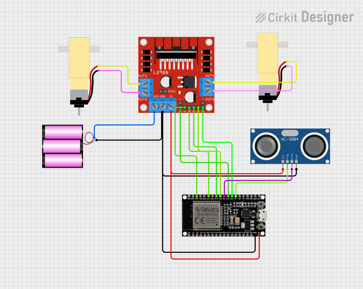
Circuit Documentation
Summary
This document provides a detailed overview of a circuit that includes two hobby gearmotors, a 12V battery, an ESP32 microcontroller, an L298N DC motor driver, and an HC-SR04 ultrasonic sensor. The circuit is designed to control the gearmotors using the motor driver, with the ESP32 providing control signals. The ultrasonic sensor is used for distance measurement, and the entire system is powered by a 12V battery.
Component List
Hobby Gearmotor with 48:1 gearbox
- Pins: pin 1, pin 2
- Description: A DC motor with a 48:1 gearbox for increased torque.
- Purpose: Provides mechanical movement.
Battery 12V
- Pins: +, -
- Description: A 12V battery for powering the circuit.
- Purpose: Supplies power to the circuit.
ESP32 38 PINS
- Pins: GND, G23, G22, TXD, RXD, G21, G19, G18, G5, G17, G16, G4, G0, G2, G15, SDI, SD0, CLK, 3V3, EN, SP, SN, G34, G35, G32, 33, G25, G26, G27, G14, G12, G13, SD2, SD3, 5V
- Description: A microcontroller with Wi-Fi and Bluetooth capabilities.
- Purpose: Provides control signals to the motor driver and reads data from the ultrasonic sensor.
L298N DC motor driver
- Pins: OUT1, OUT2, 12V, GND, 5V, OUT3, OUT4, 5V-ENA-JMP-I, 5V-ENA-JMP-O, +5V-J1, +5V-J2, ENA, IN1, IN2, IN3, IN4, ENB
- Description: A dual H-bridge motor driver.
- Purpose: Controls the direction and speed of the gearmotors.
HC-SR04 Ultrasonic Sensor
- Pins: VCC, TRIG, ECHO, GND
- Description: An ultrasonic sensor for distance measurement.
- Purpose: Measures distance to objects.
Wiring Details
Hobby Gearmotor with 48:1 gearbox (Motor 1)
- pin 1 connected to OUT2 of L298N DC motor driver
- pin 2 connected to OUT1 of L298N DC motor driver
Hobby Gearmotor with 48:1 gearbox (Motor 2)
- pin 1 connected to OUT3 of L298N DC motor driver
- pin 2 connected to OUT4 of L298N DC motor driver
Battery 12V
- + connected to 12V of L298N DC motor driver
- - connected to GND of ESP32 38 PINS, L298N DC motor driver, and HC-SR04 Ultrasonic Sensor
ESP32 38 PINS
- G22 connected to IN1 of L298N DC motor driver
- G21 connected to IN2 of L298N DC motor driver
- G19 connected to IN3 of L298N DC motor driver
- G18 connected to IN4 of L298N DC motor driver
- G5 connected to ECHO of HC-SR04 Ultrasonic Sensor
- G17 connected to ENA of L298N DC motor driver
- G16 connected to ENB of L298N DC motor driver
- G4 connected to TRIG of HC-SR04 Ultrasonic Sensor
- 5V connected to 5V of L298N DC motor driver and VCC of HC-SR04 Ultrasonic Sensor
L298N DC motor driver
- OUT2 connected to pin 1 of Hobby Gearmotor with 48:1 gearbox (Motor 1)
- OUT1 connected to pin 2 of Hobby Gearmotor with 48:1 gearbox (Motor 1)
- OUT3 connected to pin 1 of Hobby Gearmotor with 48:1 gearbox (Motor 2)
- OUT4 connected to pin 2 of Hobby Gearmotor with 48:1 gearbox (Motor 2)
- 12V connected to + of Battery 12V
- GND connected to - of Battery 12V, GND of ESP32 38 PINS, and GND of HC-SR04 Ultrasonic Sensor
- IN1 connected to G22 of ESP32 38 PINS
- IN2 connected to G21 of ESP32 38 PINS
- IN3 connected to G19 of ESP32 38 PINS
- IN4 connected to G18 of ESP32 38 PINS
- ENA connected to G17 of ESP32 38 PINS
- ENB connected to G16 of ESP32 38 PINS
- 5V connected to 5V of ESP32 38 PINS
HC-SR04 Ultrasonic Sensor
- VCC connected to 5V of ESP32 38 PINS
- TRIG connected to G4 of ESP32 38 PINS
- ECHO connected to G5 of ESP32 38 PINS
- GND connected to - of Battery 12V, GND of ESP32 38 PINS, and GND of L298N DC motor driver
Code
No code provided for this circuit.