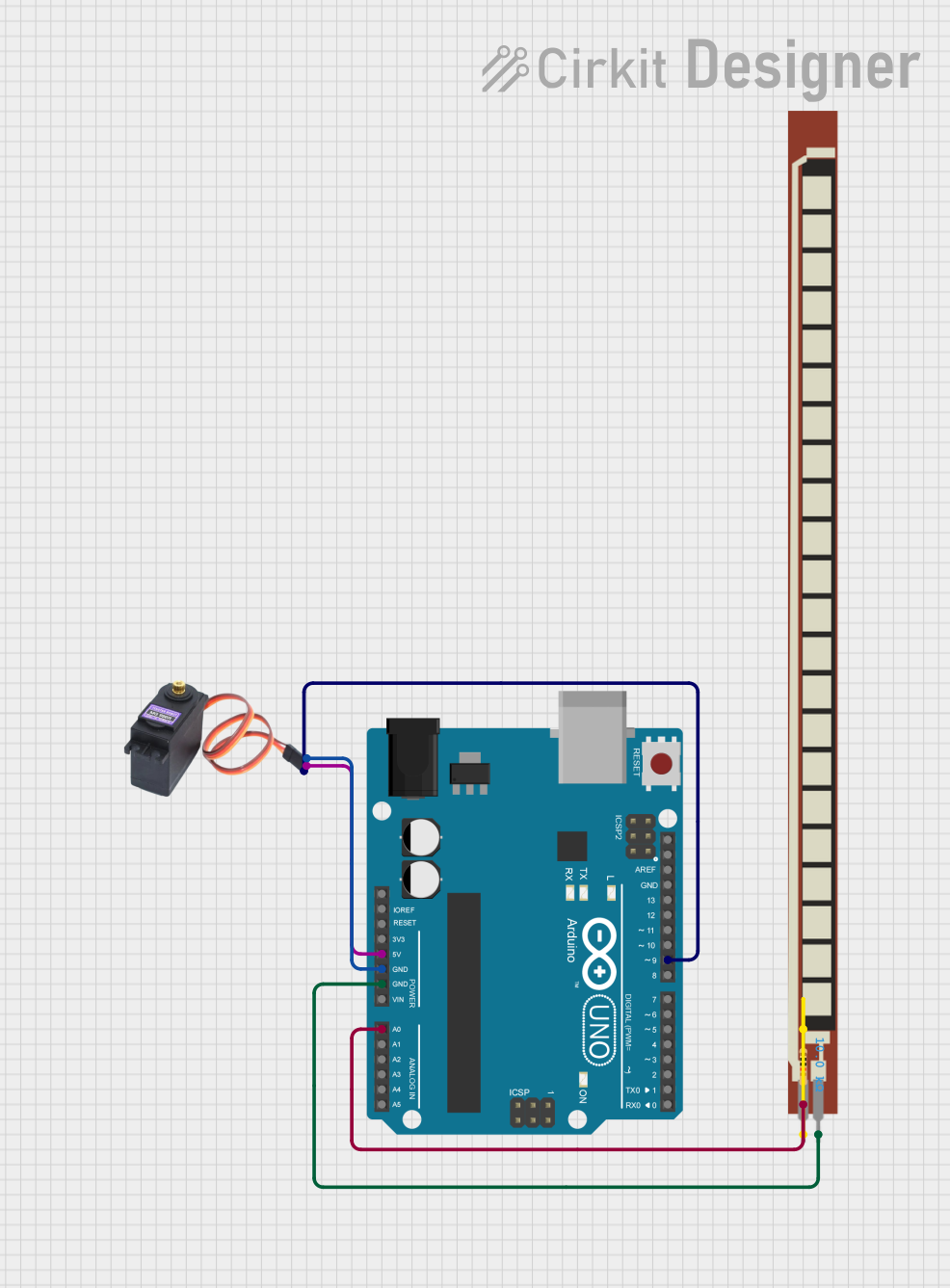
Arduino UNO Controlled Servo with Flex Sensor Feedback

Circuit Documentation
Summary of the Circuit
This circuit is designed to control a servo motor (MG996R) using an Arduino UNO based on the input from a flex sensor (Basic Flex Resistor). The servo motor's position is determined by the flex sensor's resistance, which changes when the sensor is bent. The Arduino UNO reads the analog value from the flex sensor, maps it to a corresponding servo angle, and then commands the servo to move to that position. The circuit also includes a pull-up resistor to ensure a reliable voltage level for the analog input.
Component List
Arduino UNO
- Description: A microcontroller board based on the ATmega328P.
- Purpose: Acts as the central controller for reading the flex sensor value, processing the data, and controlling the servo motor's position.
Basic Flex Resistor
- Description: A flexible resistor whose resistance changes when bent.
- Purpose: Provides analog input to the Arduino UNO to determine the servo motor's position.
MG996R (Servo Motor)
- Description: A high-torque digital servo motor.
- Purpose: Moves to a position based on the PWM signal received from the Arduino UNO.
Resistor (10k Ohms)
- Description: A fixed resistor with a resistance of 10,000 Ohms.
- Purpose: Acts as a pull-up resistor for the flex sensor to provide a stable voltage reference.
Wiring Details
Arduino UNO
- 5V: Provides power to the servo motor (MG996R VCC).
- GND: Connected to the servo motor (MG996R GND) and the flex sensor (Basic Flex Resistor Pin 2).
- A0: Receives the analog signal from the pull-up resistor network connected to the flex sensor.
- D9: Sends PWM control signal to the servo motor (MG996R SIG).
Basic Flex Resistor
- Pin 1: Connected to one end of the pull-up resistor (Resistor pin1).
- Pin 2: Connected to the Arduino UNO GND.
MG996R (Servo Motor)
- VCC: Powered by the Arduino UNO 5V.
- GND: Grounded to the Arduino UNO GND.
- SIG: Receives PWM control signal from the Arduino UNO D9.
Resistor (10k Ohms)
- pin1: Connected to the flex sensor (Basic Flex Resistor Pin 1).
- pin2: Connected to the Arduino UNO A0.
Documented Code
#include <Servo.h>

const int flexPin = A0; // Analog pin for flex sensor
const int servoPin = 9;  // PWM pin for servo motor

Servo myServo;

void setup() {
  Serial.begin(9600);
  myServo.attach(servoPin);
}

void loop() {
  int flexValue = analogRead(flexPin); // Read the flex sensor value
  int servoAngle = map(flexValue, 0, 1023, 0, 180); // Map the value to a servo angle

  myServo.write(servoAngle); // Set the servo position
  delay(15); // Small delay for the servo to reach the position

  Serial.print("Flex Value: ");
  Serial.print(flexValue);
  Serial.print(" -> Servo Angle: ");
  Serial.println(servoAngle);

  delay(100); // Delay for stability
}
File Name: sketch.ino
Description: This code initializes a Servo object and attaches it to pin D9 of the Arduino UNO. In the main loop, the analog value from the flex sensor connected to pin A0 is read and mapped to a servo angle range. The servo is then commanded to move to this angle. The flex sensor value and corresponding servo angle are printed to the serial monitor for debugging purposes.