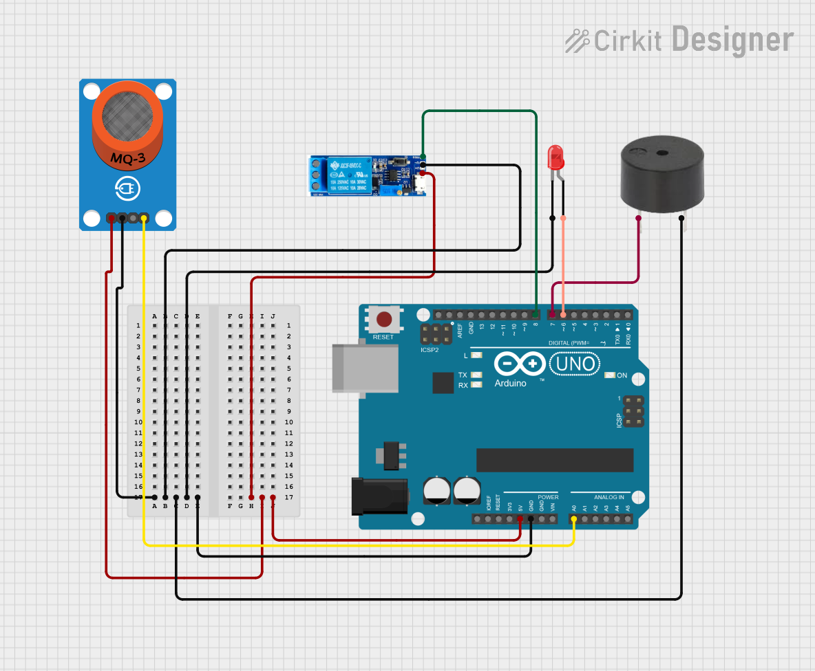
Arduino UNO Based Alcohol Detection System with Relay Control and Alerts

Circuit Documentation
Summary of the Circuit
This circuit is designed around an Arduino UNO microcontroller, which serves as the central processing unit. The circuit includes an MQ-3 alcohol sensor breakout for detecting alcohol levels, a relay module for controlling power to external devices, a buzzer for audible alerts, and an LED for visual indication. The Arduino UNO is responsible for reading the sensor data, controlling the relay, and driving the buzzer and LED based on predefined conditions.
Component List
Arduino UNO
- Description: A microcontroller board based on the ATmega328P.
- Pins: UNUSED, IOREF, Reset, 3.3V, 5V, GND, Vin, A0-A5, SCL, SDA, AREF, D0-D13.
MQ-3 Breakout
- Description: An alcohol sensor module for detecting alcohol concentration in the air.
- Pins: VCC, GND, DO, AO.
Relay Module 5V-30V
- Description: A relay module for controlling high power devices.
- Pins: Common contact, normally open, normally closed, trigger, V-, V+.
Buzzer
- Description: An electronic buzzer for producing sound.
- Pins: PIN, GND.
LED: Two Pin (red)
- Description: A red LED for visual indication.
- Pins: Cathode, Anode.
Wiring Details
Arduino UNO
- 5V connected to Relay Module V+ and MQ-3 VCC.
- GND connected to Relay Module V-, Buzzer GND, MQ-3 GND, and LED cathode.
- A0 connected to MQ-3 AO.
- D8 connected to Relay Module trigger.
- D7 connected to Buzzer PIN.
- D6 connected to LED anode.
MQ-3 Breakout
- VCC connected to Arduino UNO 5V.
- GND connected to Arduino UNO GND.
- AO connected to Arduino UNO A0.
Relay Module 5V-30V
- V+ connected to Arduino UNO 5V.
- V- connected to Arduino UNO GND.
- Trigger connected to Arduino UNO D8.
Buzzer
- PIN connected to Arduino UNO D7.
- GND connected to Arduino UNO GND.
LED: Two Pin (red)
- Anode connected to Arduino UNO D6.
- Cathode connected to Arduino UNO GND.
Documented Code
Arduino UNO Code (sketch.ino)
void setup() {
  // put your setup code here, to run once:

}

void loop() {
  // put your main code here, to run repeatedly:

}
The provided code is a template with empty setup() and loop() functions. The setup() function is intended for initialization code that runs once when the Arduino is powered on or reset. The loop() function contains the main logic of the program, which runs continuously after the setup() is complete.
Additional Notes
- The code for the Arduino UNO is currently a placeholder and needs to be implemented based on the specific requirements of the circuit's operation.
- The
documentation.txtfile is empty and does not contain any additional information.