Cirkit Designer
Your all-in-one circuit design IDE
Home /
Project Documentation
Arduino-Controlled Bluetooth Robot with Dual DC Motors and Servo Actuation

Circuit Documentation
Summary
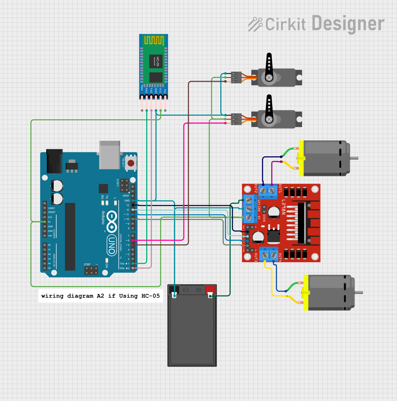
This circuit is designed to control two DC motors and two servos, with the capability to communicate via Bluetooth using an HC-05 module. The Arduino UNO serves as the central microcontroller, interfacing with an L298N DC motor driver to control the motors, and directly controlling the servos with PWM signals. The circuit is powered by a battery, with voltage regulation provided by the Arduino UNO and the L298N motor driver.
Component List
DC Motor
- Description: Electric motor that converts DC electrical power into mechanical rotation.
- Pins: pin 1, pin 2
HC-05 Bluetooth Module
- Description: Bluetooth module for wireless communication.
- Pins: Key, VCC, GND, TXD, RXD, State
Servo
- Description: A rotary actuator or linear actuator that allows for precise control of angular or linear position.
- Pins: GND, VCC, PWM
Battery
- Description: Power source for the circuit.
- Pins: -, +
Arduino UNO
- Description: Microcontroller board based on the ATmega328P.
- Pins: UNUSED, IOREF, Reset, 3.3V, 5V, GND, Vin, A0-A5, SCL, SDA, AREF, D0-D13
L298N DC Motor Driver
- Description: A motor driver module that allows for control of two DC motors.
- Pins: OUT1, OUT2, 12V, GND, 5V, OUT3, OUT4, 5V-ENA-JMP-I, 5V-ENA-JMP-O, +5V-J1, +5V-J2, ENA, IN1, IN2, IN3, IN4, ENB
Wiring Details
DC Motors
- Motor 1:
- pin 1 connected to L298N OUT2
- pin 2 connected to L298N OUT1
- Motor 2:
- pin 1 connected to L298N OUT4
- pin 2 connected to L298N OUT3
HC-05 Bluetooth Module
- VCC connected to Arduino UNO 5V
- GND connected to Arduino UNO GND
- TXD connected to Arduino UNO D0
- RXD connected to Arduino UNO D1
Servos
- Servo 1:
- VCC connected to Arduino UNO 5V
- GND connected to Arduino UNO GND
- PWM connected to Arduino UNO D6
- Servo 2:
- VCC connected to Arduino UNO 5V
- GND connected to Arduino UNO GND
- PWM connected to Arduino UNO D5
Battery
- connected to L298N 12V
- connected to Arduino UNO GND
Arduino UNO
- 5V output to power servos, HC-05, and L298N 5V
- GND connected to battery -, servos GND, HC-05 GND, and L298N GND
- D13 connected to L298N IN1
- D12 connected to L298N IN2
- D11 connected to L298N IN3
- D10 connected to L298N IN4
- D6 connected to Servo 1 PWM
- D5 connected to Servo 2 PWM
- D1 connected to HC-05 RXD
- D0 connected to HC-05 TXD
L298N DC Motor Driver
- 5V connected to Arduino UNO 5V
- GND connected to Arduino UNO GND
- 12V connected to battery +
- IN1 connected to Arduino UNO D13
- IN2 connected to Arduino UNO D12
- IN3 connected to Arduino UNO D11
- IN4 connected to Arduino UNO D10
- OUT1 connected to DC Motor 1 pin 2
- OUT2 connected to DC Motor 1 pin 1
- OUT3 connected to DC Motor 2 pin 2
- OUT4 connected to DC Motor 2 pin 1
Documented Code
Arduino UNO Code (sketch.ino)
void setup() {
  // put your setup code here, to run once:

}

void loop() {
  // put your main code here, to run repeatedly:

}
Note: The provided code is a template and does not contain any functional code to control the motors or communicate via Bluetooth. The user must implement the setup and loop functions to initialize the pins and define the behavior of the circuit.