Cirkit Designer
Your all-in-one circuit design IDE
Home /
Project Documentation
ESP32-Based Wi-Fi Controlled Smart Irrigation System
Circuit Documentation
Summary
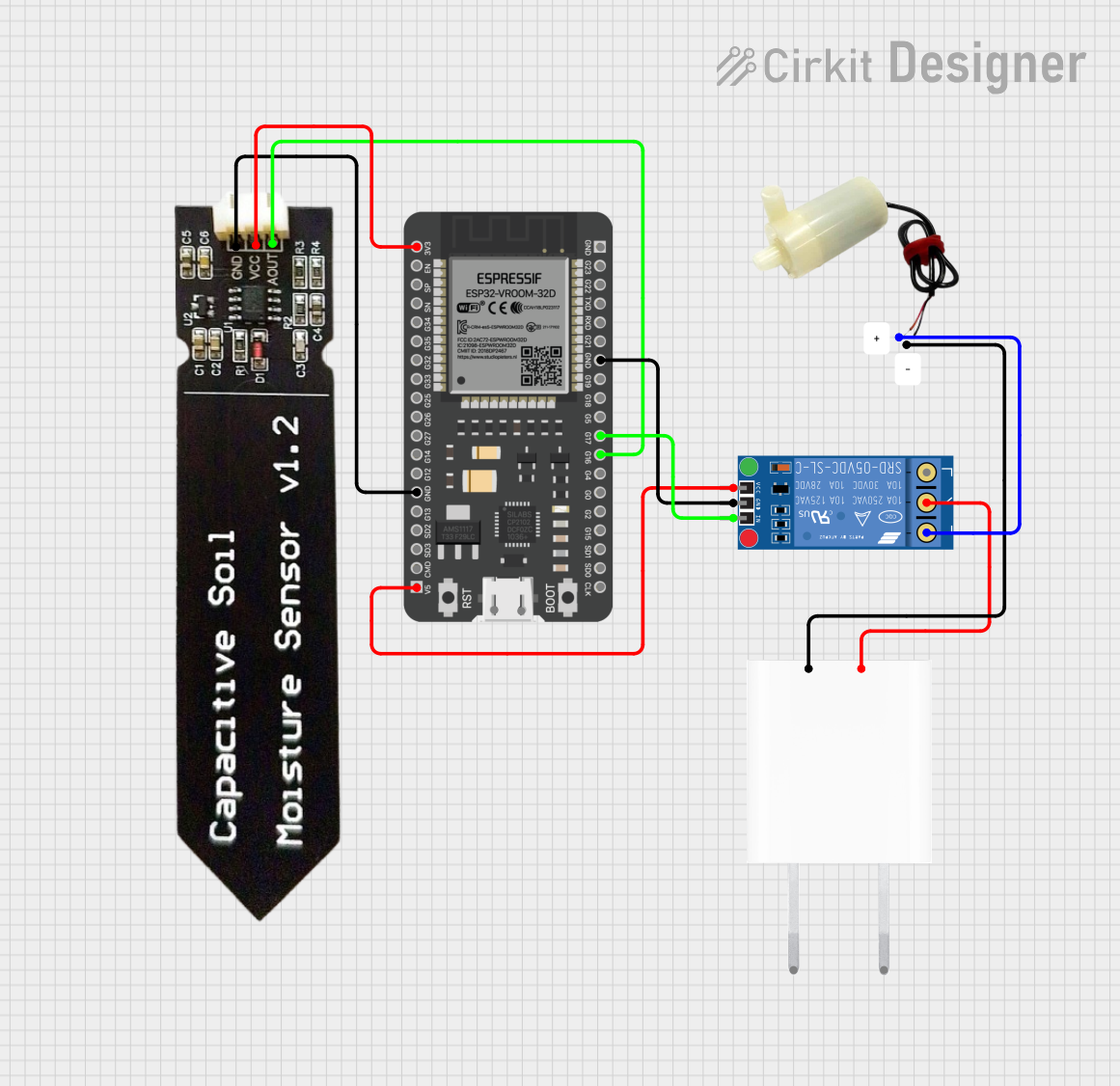
This document provides a detailed overview of a circuit designed to monitor soil moisture levels and control a water pump based on the moisture readings. The circuit utilizes an ESP32 microcontroller, a capacitive soil moisture sensor, a relay module, a 5V mini water pump, and a 5V adapter. The ESP32 reads the soil moisture levels and controls the relay to activate the water pump when necessary.
Component List
ESP32 - 38 pins
- Description: A versatile microcontroller with Wi-Fi and Bluetooth capabilities.
- Pins: 3V3, EN, SP, SN, G34, G35, G32, G33, G25, G26, G27, G14, G12, GND, G13, SD2, SD3, CMD, 5V, G23, G22, TXD, RXD, G21, G19, G18, G5, G17, G16, G4, G0, G2, G15, SD1, SD0, CLK
Capacitive Soil Moisture Sensor V1.2
- Description: A sensor that measures soil moisture levels.
- Pins: GND, VCC, AOUT
KF-301 Relay
- Description: A relay module used to control high-power devices.
- Pins: signal, power, ground, NC, C, NO
5V Mini Water Pump
- Description: A small water pump powered by 5V.
- Pins: positive pin, negative pin
5V Adapter
- Description: A power adapter that provides 5V output.
- Pins: AC In 1, AC In 2, 5V, GND
Wiring Details
ESP32 - 38 pins
- 3V3: Connected to VCC of the Capacitive Soil Moisture Sensor.
- GND: Connected to GND of the Capacitive Soil Moisture Sensor and ground of the KF-301 Relay.
- 5V: Connected to power of the KF-301 Relay.
- G17: Connected to signal of the KF-301 Relay.
- G16: Connected to AOUT of the Capacitive Soil Moisture Sensor.
Capacitive Soil Moisture Sensor V1.2
- VCC: Connected to 3V3 of the ESP32.
- GND: Connected to GND of the ESP32.
- AOUT: Connected to G16 of the ESP32.
KF-301 Relay
- power: Connected to 5V of the ESP32.
- ground: Connected to GND of the ESP32.
- signal: Connected to G17 of the ESP32.
- C: Connected to 5V of the 5V Adapter.
- NO: Connected to positive pin of the 5V Mini Water Pump.
5V Mini Water Pump
- positive pin: Connected to NO of the KF-301 Relay.
- negative pin: Connected to GND of the 5V Adapter.
5V Adapter
- 5V: Connected to C of the KF-301 Relay.
- GND: Connected to negative pin of the 5V Mini Water Pump.
Code
There is no code provided for the microcontrollers in this circuit.