
Arduino UNO Smart Irrigation System with DHT11, Water Level, and Soil Moisture Sensors
View and Edit Project In Cirkit Designer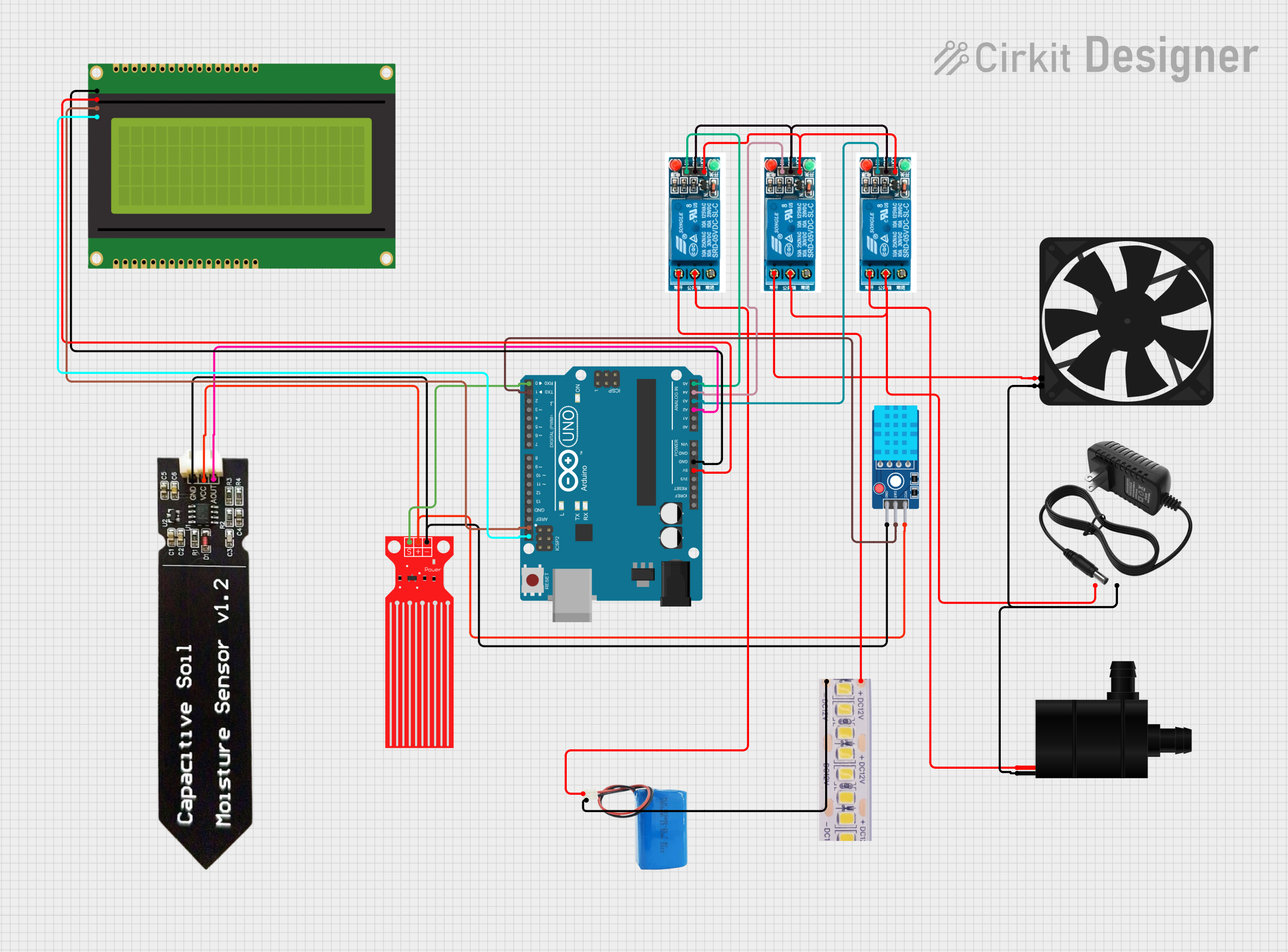
Circuit Documentation
Summary
This circuit is designed to control a water pump, light, and fan using relays based on input from a DHT11 sensor, water level sensor, and a capacitive soil moisture sensor. The status of the system is displayed on a 20x4 I2C LCD panel. The Arduino UNO microcontroller is used to process the sensor data and control the relays.
Component List
DHT11 Sensor V2
- Description: Temperature and humidity sensor.
- Pins: GND, DAT, VCC
Fan
- Description: Cooling fan.
- Pins: GND, 5V
5V Battery
- Description: Power source.
- Pins: Positive, Negative
5V Relay
- Description: Relay module for switching devices.
- Pins: Normally Open, Common Terminal, Normally Closed, In, GND, VCC
Water Level Sensor
- Description: Sensor to detect water level.
- Pins: SIG, VCC, GND
Capacitive Soil Moisture Sensor V1.2
- Description: Sensor to measure soil moisture.
- Pins: GND, VCC, AOUT
12V Power Supply
- Description: Power source.
- Pins: +, -
Water Pump
- Description: Pump for water circulation.
- Pins: VCC, GND
12V White LED Strip
- Description: LED strip for lighting.
- Pins: +12V, GND
Arduino UNO
- Description: Microcontroller for processing and control.
- Pins: UNUSED, IOREF, Reset, 3.3V, 5V, GND, Vin, A0, A1, A2, A3, A4, A5, SCL, SDA, AREF, D13, D12, D11, D10, D9, D8, D7, D6, D5, D4, D3, D2, D1, D0
20x4 I2C LCD Panel
- Description: Display panel for showing status.
- Pins: GND, VCC, SDA, SCL
Wiring Details
DHT11 Sensor V2
- GND: Connected to GND of Water Level Sensor and Capacitive Soil Moisture Sensor.
- DAT: Connected to D1 of Arduino UNO.
- VCC: Connected to VCC of Water Level Sensor and Capacitive Soil Moisture Sensor.
Fan
- GND: Connected to GND of 12V Power Supply and Water Pump.
- 5V: Connected to Normally Open pin of 5V Relay.
5V Battery
- Positive: Connected to Common Terminal of 5V Relay.
- Negative: Connected to GND of 12V White LED Strip.
5V Relay
- Normally Open: Connected to +12V of 12V White LED Strip.
- Common Terminal: Connected to Positive of 5V Battery.
- In: Connected to A5 of Arduino UNO.
- GND: Connected to GND of other 5V Relays.
- VCC: Connected to VCC of other 5V Relays.
Water Level Sensor
- SIG: Connected to D0 of Arduino UNO.
- VCC: Connected to VCC of DHT11 Sensor V2 and Capacitive Soil Moisture Sensor.
- GND: Connected to GND of DHT11 Sensor V2 and Capacitive Soil Moisture Sensor.
Capacitive Soil Moisture Sensor V1.2
- GND: Connected to GND of DHT11 Sensor V2 and Water Level Sensor.
- VCC: Connected to VCC of DHT11 Sensor V2 and Water Level Sensor.
- AOUT: Connected to A2 of Arduino UNO.
12V Power Supply
- +: Connected to Common Terminal of 5V Relay.
- -: Connected to GND of Water Pump and Fan.
Water Pump
- VCC: Connected to Normally Open pin of 5V Relay.
- GND: Connected to GND of 12V Power Supply and Fan.
12V White LED Strip
- +12V: Connected to Normally Open pin of 5V Relay.
- GND: Connected to Negative of 5V Battery.
Arduino UNO
- D1: Connected to DAT of DHT11 Sensor V2.
- A5: Connected to In of 5V Relay.
- A4: Connected to In of 5V Relay.
- A3: Connected to In of 5V Relay.
- A2: Connected to AOUT of Capacitive Soil Moisture Sensor V1.2.
- D0: Connected to SIG of Water Level Sensor.
- 5V: Connected to VCC of 20x4 I2C LCD Panel.
- GND: Connected to GND of 20x4 I2C LCD Panel.
- SCL: Connected to SCL of 20x4 I2C LCD Panel.
- SDA: Connected to SDA of 20x4 I2C LCD Panel.
20x4 I2C LCD Panel
- GND: Connected to GND of Arduino UNO.
- VCC: Connected to 5V of Arduino UNO.
- SDA: Connected to SDA of Arduino UNO.
- SCL: Connected to SCL of Arduino UNO.
Code Documentation
/*
 * Arduino Sketch for controlling a pump, light, and fan using relays
 * based on input from a DHT11 sensor, water level sensor, and a capacitive
 * soil moisture sensor. The status is displayed on a 20x4 I2C LCD panel.
 */

#include <Wire.h>
#include <LiquidCrystal_I2C.h>
#include <DHT.h>
#include <TimeLib.h>

// Pin definitions
#define DHTPIN 7
#define DHTTYPE DHT11
#define RELAY_PUMP A3
#define RELAY_LIGHT A5
#define RELAY_FAN A4
#define WATER_SENSOR_PIN A1
#define SOIL_SENSOR_PIN A2

// Initialize sensors and display
DHT dht(DHTPIN, DHTTYPE);
LiquidCrystal_I2C lcd(0x27, 20, 4);

void setup() {
  Serial.begin(9600);
  dht.begin();
  lcd.init();
  lcd.backlight();
  pinMode(RELAY_PUMP, OUTPUT);
  pinMode(RELAY_LIGHT, OUTPUT);
  pinMode(RELAY_FAN, OUTPUT);
  digitalWrite(RELAY_PUMP, LOW);
  digitalWrite(RELAY_LIGHT, LOW);
  digitalWrite(RELAY_FAN, LOW);
  setTime(12, 0, 0, 1, 1, 2023);
}

void loop() {
  float h = dht.readHumidity();
  float t = dht.readTemperature();
  int waterLevel = analogRead(WATER_SENSOR_PIN);
  int soilMoisture = analogRead(SOIL_SENSOR_PIN);

  if (isnan(h) || isnan(t)) {
    Serial.println("Failed to read from DHT sensor!");
    return;
  }

  lcd.clear();
  lcd.setCursor(0, 0);
  lcd.print("Temp: "); lcd.print(t); lcd.print(" C");
  lcd.setCursor(0, 1);
  lcd.print("Humidity: "); lcd.print(h); lcd.print(" %");
  lcd.setCursor(0, 2);
  lcd.print("Water Level: "); lcd.print(waterLevel);
  lcd.setCursor(0, 3);
  lcd.print("Soil Moisture: "); lcd.print(soilMoisture);

  if (t > 25) {
    digitalWrite(RELAY_FAN, HIGH);
  } else {
    digitalWrite(RELAY_FAN, LOW);
  }
  if (h > 60 || waterLevel < 500 || soilMoisture < 300) {
    digitalWrite(RELAY_PUMP, HIGH);
  } else {
    digitalWrite(RELAY_PUMP, LOW);
  }
  if (hour() >= 18 || hour() < 6) {
    digitalWrite(RELAY_LIGHT, HIGH);
  } else {
    digitalWrite(RELAY_LIGHT, LOW);
  }
  delay(2000);
}
This code initializes the sensors and the LCD display, reads the sensor values, and controls the relays based on the sensor inputs. The status is displayed on the LCD panel, and the relays are activated or deactivated based on the conditions specified in the code.