
Circuit Documentation
Summary
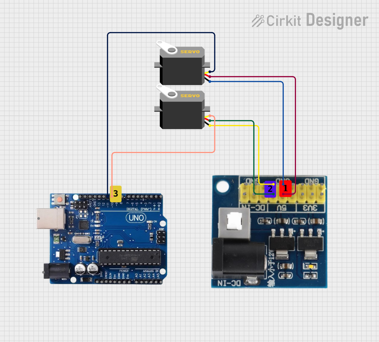
The circuit in question is designed to control two servo motors using an Arduino Uno R3 microcontroller. The servos are powered by a voltage regulator that steps down the voltage from 12V to 5V. The Arduino Uno R3 sends pulse-width modulation (PWM) signals to the servos to control their position. The circuit also includes ground connections between the servos and the voltage regulator.
Component List
Servo
- Description: A servo is an actuator that allows for precise control of angular or linear position, velocity, and acceleration. It consists of a suitable motor coupled to a sensor for position feedback.
- Pins:
gnd- Ground connection.vcc- Power supply (5V).pulse- PWM signal input to control the servo's position.
Arduino Uno R3
- Description: The Arduino Uno R3 is a microcontroller board based on the ATmega328P. It has 14 digital input/output pins, 6 analog inputs, a USB connection, a power jack, an ICSP header, and a reset button.
- Pins:
USB Port,Power Jack,Not Connected,IOREF,RESET,3.3V,5V,GND,VIN,A0toA5,SCL,SDA,AREF, and digital pins0to13.
Voltage Regulator 12V to 5V/3V
- Description: This component steps down the input voltage of 12V to output voltages of 5V and 3V, suitable for powering various electronic components.
- Pins:
gnd- Ground connection.dc in1,dc in2,dc in3- Input pins for 12V.v6 5v,v5 5v,v4 5v- Output pins providing 5V.v3 3v,v2 3v,v1 3v- Output pins providing 3V.
Comment
- Description: A comment component is typically used in circuit diagrams to provide additional information about the circuit or specific components.
Wiring Details
Servo 1
- Ground: Connected to the ground pin (
gnd) of the Voltage Regulator. - Power Supply (VCC): Connected to the 5V output pin (
v5 5v) of the Voltage Regulator. - Control Signal (Pulse): Connected to digital pin
11of the Arduino Uno R3.
Servo 2
- Ground: Connected to the ground pin (
gnd) of the Voltage Regulator. - Power Supply (VCC): Connected to the 5V output pin (
v6 5v) of the Voltage Regulator. - Control Signal (Pulse): Connected to digital pin
10of the Arduino Uno R3.
Arduino Uno R3
- Digital Pin 11: Sends PWM signal to Servo 1.
- Digital Pin 10: Sends PWM signal to Servo 2.
Voltage Regulator 12V to 5V/3V
- Ground: Provides ground connection to both Servo 1 and Servo 2.
- 5V Outputs: Provides power to both Servo 1 and Servo 2.
Documented Code
No code was provided for the microcontroller. The documentation of the code would typically include the setup and loop functions for the Arduino sketch, along with any functions used to control the servos. Since no code is available, this section cannot be completed. If code becomes available, it should be documented here with explanations of its functionality and how it interfaces with the hardware components listed above.