Cirkit Designer
Your all-in-one circuit design IDE
Home /
Project Documentation
Arduino-Controlled Relay for AC LED Bulb Switching
Circuit Documentation
Summary
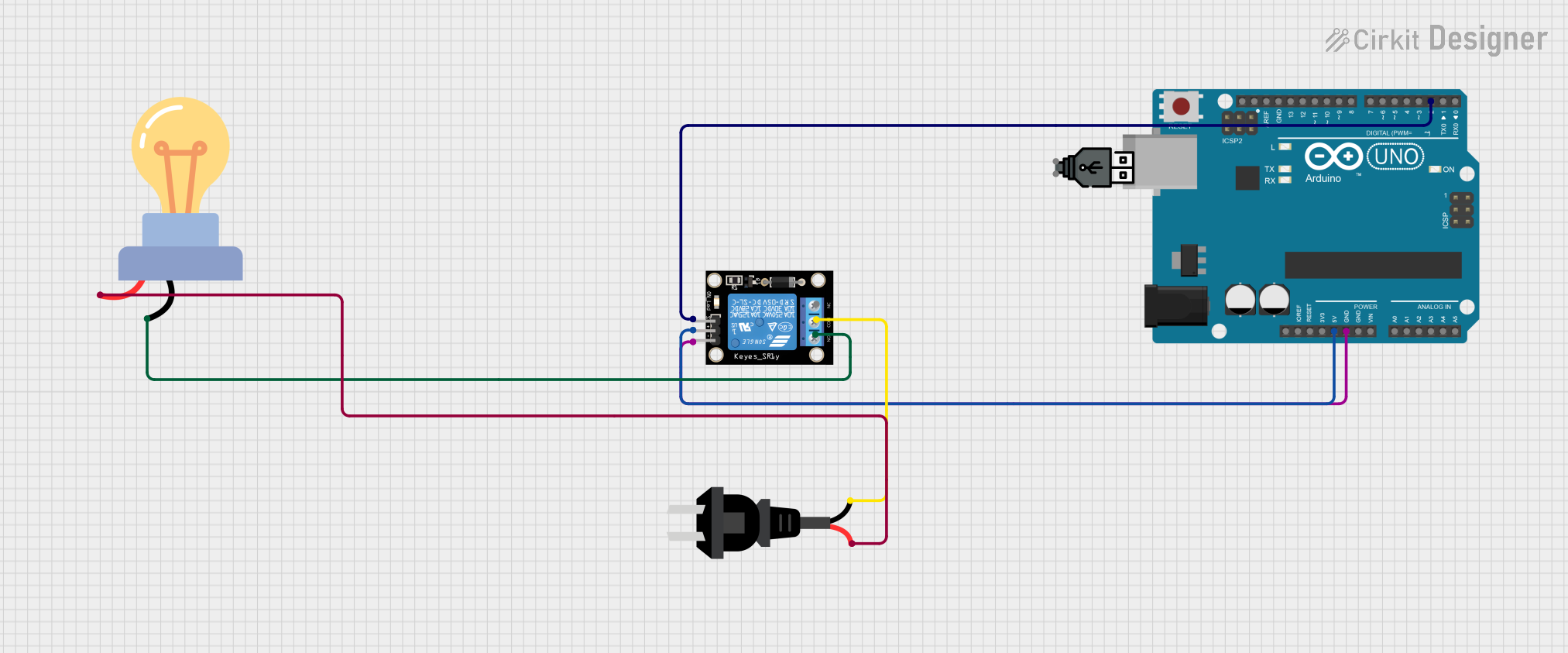
This circuit is designed to control an AC-powered LED bulb using an Arduino UNO microcontroller and a single-channel relay module. The Arduino UNO is responsible for sending control signals to the relay, which in turn switches the LED bulb on or off. The relay module isolates the low-voltage control circuitry from the high-voltage AC side, providing safety and compatibility between the two systems.
Component List
Arduino UNO
- Description: A microcontroller board based on the ATmega328P.
- Purpose: Acts as the control unit for the circuit, sending signals to the relay module.
- Pins: UNUSED, IOREF, Reset, 3.3V, 5V, GND, Vin, A0-A5, SCL, SDA, AREF, D0-D13.
Relay Module 1 Channel
- Description: An electromechanical switch that can be controlled by a digital signal from the Arduino UNO.
- Purpose: Switches the AC current to the LED bulb on or off.
- Pins: S (Signal), 5V, GND, NC (Normally Closed), COM (Common), NO (Normally Open).
AC Source
- Description: Provides alternating current to power the LED bulb.
- Purpose: Supplies the necessary power for the LED bulb when the relay is activated.
- Pins: -, +.
LED Bulb AC
- Description: An LED light bulb designed for AC power.
- Purpose: The load in the circuit, which is to be switched on or off by the relay.
- Pins: +, -.
USB Power
- Description: A power source that provides DC power through a USB connection.
- Purpose: Powers the Arduino UNO.
- Pins: +, -.
Wiring Details
Arduino UNO
- 5V connected to Relay Module 5V.
- GND connected to Relay Module GND.
- D2 connected to Relay Module S (Signal).
Relay Module 1 Channel
- 5V connected to Arduino UNO 5V.
- GND connected to Arduino UNO GND.
- S (Signal) connected to Arduino UNO D2.
- COM (Common) connected to AC Source -.
- NO (Normally Open) connected to LED Bulb AC -.
AC Source
- - connected to Relay Module COM (Common).
- + connected to LED Bulb AC +.
LED Bulb AC
- + connected to AC Source +.
- - connected to Relay Module NO (Normally Open).
Documented Code
Arduino UNO Code (sketch.ino)
void setup() {
  // put your setup code here, to run once:

}

void loop() {
  // put your main code here, to run repeatedly:

}
Note: The provided code is a template and does not contain any functional code to control the relay module. The user must implement the control logic within the setup() and loop() functions.
Additional Files
- documentation.txt: This file is mentioned in the code input but contains no content. It is likely intended for additional notes or manual documentation by the user.