Cirkit Designer
Your all-in-one circuit design IDE
Home /
Project Documentation
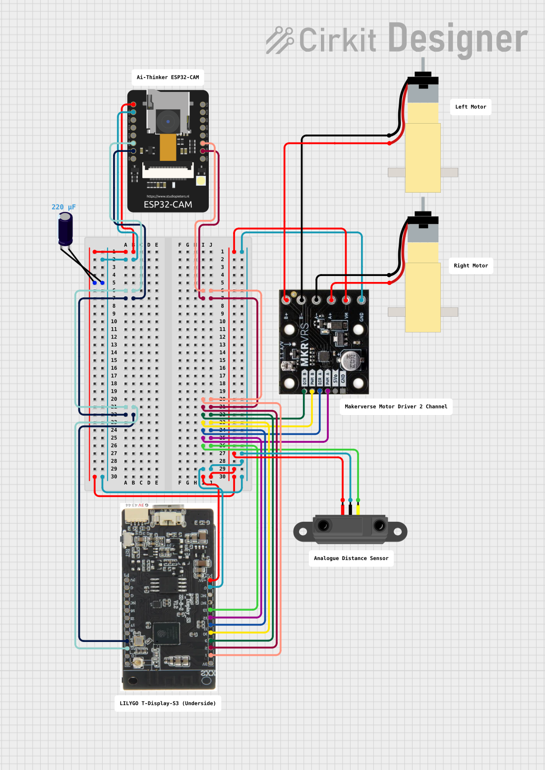
ESP32-CAM and T-Display-S3 Based Obstacle-Avoiding Robot
Circuit Documentation
Summary of the Circuit
This circuit integrates various components to perform a set of functions that are not explicitly defined by the input data. However, based on the components used and their interconnections, we can infer that the circuit likely involves image capture or video streaming (ESP32-CAM), display capabilities (T-Display-S3), motion control (Motor Driver 2 Channel with Hobby Gearmotors), and proximity sensing (Infrared Proximity Sensor). The Electrolytic Capacitor is likely used for power supply stabilization.
Component List
T-Display-S3
- Description: A display module with multiple GPIO pins for interfacing with other devices.
- Pins: 3V, 1, 2, 3, 10, 11, 12, 13, GND, 5V, 43, 44, 18, 17, 21, 16
ESP32 - CAM
- Description: A camera module with Wi-Fi capabilities, suitable for IoT applications.
- Pins: 5V, GND, IO12, IO13, IO15, IO14, IO2, IO4, VOT, VOR, VCC, IO0, IO16, 3V3
Electrolytic Capacitor
- Description: A capacitor used for filtering and power stabilization.
- Pins: -, +
- Properties: Capacitance: 0.00022 Farads
Infrared Proximity Sensor
- Description: A sensor that detects the presence of objects within a certain range without physical contact.
- Pins: Vout, GND, Vcc
Motor Driver 2 Channel
- Description: A module that can control two motors independently, including direction and speed.
- Pins: DIR B, PWM B, DIR A, PWM A, 5Vo, GND, B+, B-, A-, A+, VM
Hobby Gearmotor with 48:1 gearbox (Two Instances)
- Description: A motor with a gearbox that provides a high torque output.
- Pins: pin 1, pin 2
Wiring Details
T-Display-S3
- 5V connected to ESP32 - CAM (5V), Electrolytic Capacitor (+), Motor Driver 2 Channel (VM), Infrared Proximity Sensor (Vcc)
- GND connected to ESP32 - CAM (GND), Electrolytic Capacitor (-), Motor Driver 2 Channel (GND), Infrared Proximity Sensor (GND)
- Pin 43 connected to ESP32 - CAM (IO14)
- Pin 1 connected to ESP32 - CAM (VOR)
- Pin 44 connected to ESP32 - CAM (IO2)
- Pin 2 connected to ESP32 - CAM (VOT)
- Pin 3 connected to Motor Driver 2 Channel (DIR B)
- Pin 10 connected to Motor Driver 2 Channel (PWM B)
- Pin 11 connected to Motor Driver 2 Channel (DIR A)
- Pin 12 connected to Motor Driver 2 Channel (PWM A)
- Pin 13 connected to Infrared Proximity Sensor (Vout)
ESP32 - CAM
- IO14 connected to T-Display-S3 (43)
- VOR connected to T-Display-S3 (1)
- IO2 connected to T-Display-S3 (44)
- VOT connected to T-Display-S3 (2)
Electrolytic Capacitor
- connected to ESP32 - CAM (5V), Motor Driver 2 Channel (VM), Infrared Proximity Sensor (Vcc), T-Display-S3 (5V)
- connected to ESP32 - CAM (GND), Motor Driver 2 Channel (GND), Infrared Proximity Sensor (GND), T-Display-S3 (GND)
Infrared Proximity Sensor
- Vcc connected to T-Display-S3 (5V)
- GND connected to T-Display-S3 (GND)
- Vout connected to T-Display-S3 (13)
Motor Driver 2 Channel
- VM connected to T-Display-S3 (5V)
- GND connected to T-Display-S3 (GND)
- DIR B connected to T-Display-S3 (3)
- PWM B connected to T-Display-S3 (10)
- DIR A connected to T-Display-S3 (11)
- PWM A connected to T-Display-S3 (12)
- B+ connected to Hobby Gearmotor (pin 2)
- B- connected to Hobby Gearmotor (pin 1)
- A- connected to Hobby Gearmotor (pin 1)
- A+ connected to Hobby Gearmotor (pin 2)
Hobby Gearmotor with 48:1 gearbox
- pin 1 connected to Motor Driver 2 Channel (B- or A-)
- pin 2 connected to Motor Driver 2 Channel (B+ or A+)
Documented Code
No code was provided for the microcontrollers in the circuit. Therefore, this section is not applicable for the current documentation.