
Circuit Documentation
Summary
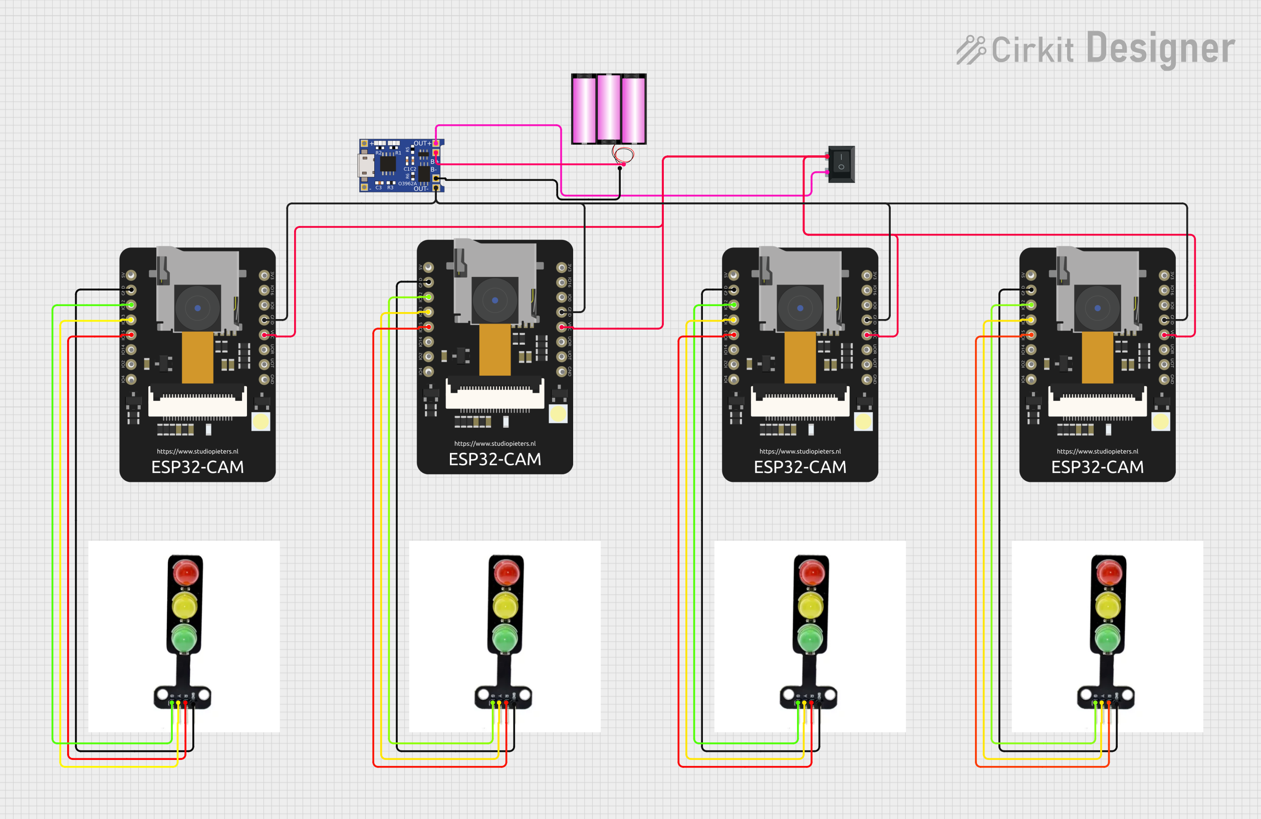
The circuit in question appears to be designed for controlling multiple traffic light modules using ESP32 CAM microcontrollers. Each ESP32 CAM is responsible for driving the LEDs of a traffic light module, with separate control lines for the red, yellow, and green LEDs. The circuit includes a battery for power, a TP4056 charging module for charging the battery, and a rocker switch to control the power flow to the ESP32 CAMs and traffic light modules.
Component List
ESP32 CAM
- Description: A microcontroller module with Wi-Fi and camera capabilities.
- Pins: 5V, GND, GPIO12, GPIO13, GPIO15, GPIO14, GPIO2, GPIO4, 3.3V, GPIO16, GPIO0, 3.3V / 5V / P_OUT, GPIO3 / RX, GPIO1 / TX
Battery 12V
- Description: A 12V power source for the circuit.
- Pins: +, -
TP4056
- Description: A lithium battery charging module.
- Pins: OUT-, B-, B+, OUT+, IN-, IN+
Rocker Switch (SPST)
- Description: A single-pole single-throw switch to control power.
- Pins: 1, 2
Traffic Light Module
- Description: A module with LEDs representing a traffic light.
- Pins: GND, RED, YELLOW, GREEN
Wiring Details
ESP32 CAM
- GND: Connected to the ground of the traffic light module and the GND pin of other ESP32 CAMs.
- GPIO12: Connected to the GREEN pin of the traffic light module.
- GPIO13: Connected to the YELLOW pin of the traffic light module.
- GPIO15: Connected to the RED pin of the traffic light module.
- 3.3V / 5V / P_OUT: Connected to the rocker switch and other ESP32 CAMs for power distribution.
Battery 12V
- +: Connected to the B+ pin of the TP4056 charging module.
- -: Connected to the B- pin of the TP4056 charging module.
TP4056
- OUT-: Connected to the GND pin of the ESP32 CAMs.
- OUT+: Connected to pin 1 of the Rocker Switch (SPST).
Rocker Switch (SPST)
- Pin 1: Connected to the OUT+ of the TP4056.
- Pin 2: Connected to the 3.3V / 5V / P_OUT of the ESP32 CAMs.
Traffic Light Module
- GND: Connected to the GND pin of the ESP32 CAM.
- RED: Connected to GPIO15 of the ESP32 CAM.
- YELLOW: Connected to GPIO13 of the ESP32 CAM.
- GREEN: Connected to GPIO12 of the ESP32 CAM.
Documented Code
No code was provided for the microcontrollers. The expected behavior would be for the ESP32 CAMs to control the traffic light modules by setting the GPIO pins high or low to turn the corresponding LEDs on or off. Without the code, the specific logic for traffic light sequencing cannot be documented.
Please note that the documentation above is based on the provided parts list and electrical net list. The actual functionality of the circuit would be determined by the embedded code running on the ESP32 CAMs, which has not been provided.