
Arduino UNO-Based IR Sensor and LCD Display System with Servo Control
View and Edit Project In Cirkit Designer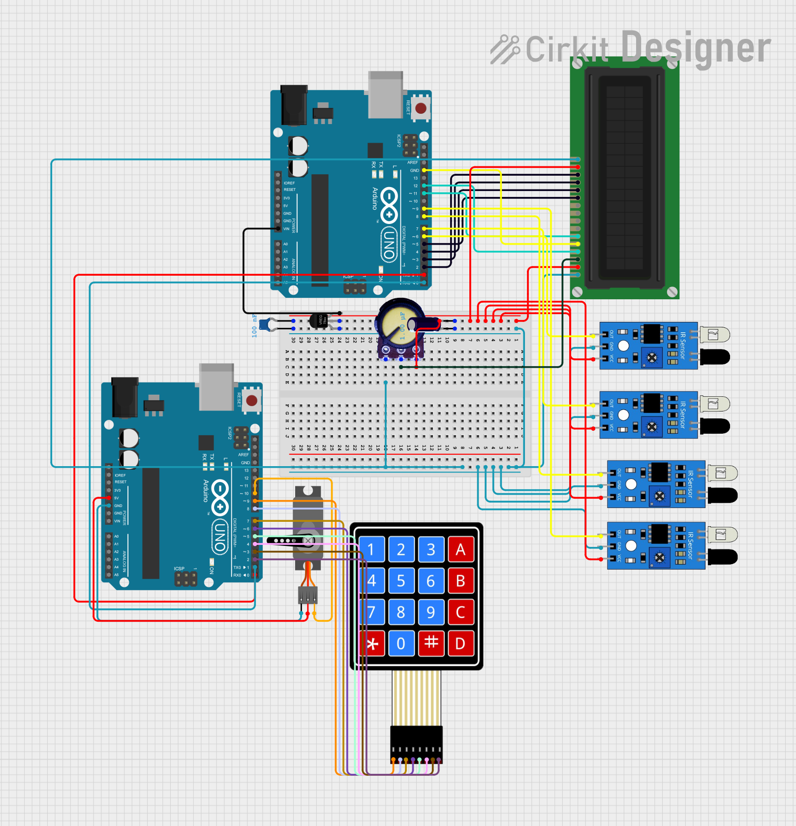
Circuit Documentation
Summary
This circuit involves two Arduino UNO microcontrollers, an LCD Display, multiple IR sensors, a potentiometer, capacitors, a servo motor, a voltage regulator, and a 4x4 membrane matrix keypad. The circuit is designed to interface various sensors and actuators with the Arduino microcontrollers, allowing for data display on the LCD and control via the keypad.
Component List
Arduino UNO
- Description: A microcontroller board based on the ATmega328P.
- Pins: UNUSED, IOREF, Reset, 3.3V, 5V, GND, Vin, A0, A1, A2, A3, A4, A5, SCL, SDA, AREF, D13, D12, D11, D10, D9, D8, D7, D6, D5, D4, D3, D2, D1, D0
LCD Display (16 pin)
- Description: A 16x2 character LCD display.
- Pins: VSS, VDD, VO, RS, R_W, E, DB0, DB1, DB2, DB3, DB4, DB5, DB6, DB7, A, K
IR Sensor
- Description: An infrared sensor for object detection.
- Pins: out, gnd, vcc
Potentiometer
- Description: A variable resistor used to adjust voltage.
- Pins: GND, Output, VCC
Ceramic Capacitor
- Description: A capacitor with a capacitance of 0.1 µF.
- Pins: pin0, pin1
Servo
- Description: A servo motor for precise control of angular position.
- Pins: GND, VCC, PWM
Voltage Regulator
- Description: A component to regulate voltage.
- Pins: GND, IN, OUT
Electrolytic Capacitor
- Description: A capacitor with a capacitance of 1 µF.
- Pins: -, +
4X4 Membrane Matrix Keypad
- Description: A keypad with 4 rows and 4 columns.
- Pins: R1, R2, R3, R4, C1, C2, C3, C4
Wiring Details
Arduino UNO
- Vin: Connected to Voltage Regulator (OUT)
- GND: Connected to LCD Display (R_W)
- D12: Connected to LCD Display (RS)
- D11: Connected to LCD Display (E)
- D9: Connected to IR Sensor (out)
- D8: Connected to IR Sensor (out)
- D7: Connected to IR Sensor (out)
- D6: Connected to IR Sensor (out)
- D5: Connected to LCD Display (DB4)
- D4: Connected to LCD Display (DB5)
- D3: Connected to LCD Display (DB6)
- D2: Connected to LCD Display (DB7)
- D1: Connected to Arduino UNO (D0)
- D0: Connected to Arduino UNO (D1)
LCD Display (16 pin)
- VSS: Connected to GND
- VDD: Connected to VCC
- VO: Connected to Potentiometer (Output)
- RS: Connected to Arduino UNO (D12)
- R_W: Connected to GND
- E: Connected to Arduino UNO (D11)
- DB4: Connected to Arduino UNO (D5)
- DB5: Connected to Arduino UNO (D4)
- DB6: Connected to Arduino UNO (D3)
- DB7: Connected to Arduino UNO (D2)
- A: Connected to VCC
- K: Connected to GND
IR Sensor
- out: Connected to Arduino UNO (D9, D8, D7, D6)
- gnd: Connected to GND
- vcc: Connected to VCC
Potentiometer
- GND: Connected to GND
- Output: Connected to LCD Display (VO)
- VCC: Connected to VCC
Ceramic Capacitor
- pin0: Connected to GND
- pin1: Connected to VCC
Servo
- VCC: Connected to Arduino UNO (5V)
- GND: Connected to GND
- PWM: Connected to Arduino UNO (D10)
Voltage Regulator
- GND: Connected to GND
- IN: Connected to VCC
- OUT: Connected to Arduino UNO (Vin)
Electrolytic Capacitor
- -: Connected to GND
- +: Connected to VCC
4X4 Membrane Matrix Keypad
- R1: Connected to Arduino UNO (D9)
- R2: Connected to Arduino UNO (D8)
- R3: Connected to Arduino UNO (D7)
- R4: Connected to Arduino UNO (D6)
- C1: Connected to Arduino UNO (D5)
- C2: Connected to Arduino UNO (D4)
- C3: Connected to Arduino UNO (D3)
- C4: Connected to Arduino UNO (D2)
Documented Code
Arduino UNO (Instance 1)
void setup() {
  // put your setup code here, to run once:

}

void loop() {
  // put your main code here, to run repeatedly:

}
Arduino UNO (Instance 2)
void setup() {
  // put your setup code here, to run once:

}

void loop() {
  // put your main code here, to run repeatedly:

}
This documentation provides a comprehensive overview of the circuit, including a summary, detailed component list, wiring details, and documented code for the microcontrollers.