Arduino Nano Based GPS Tracker with GSM Module and Panic Buttons
Circuit Documentation
Summary
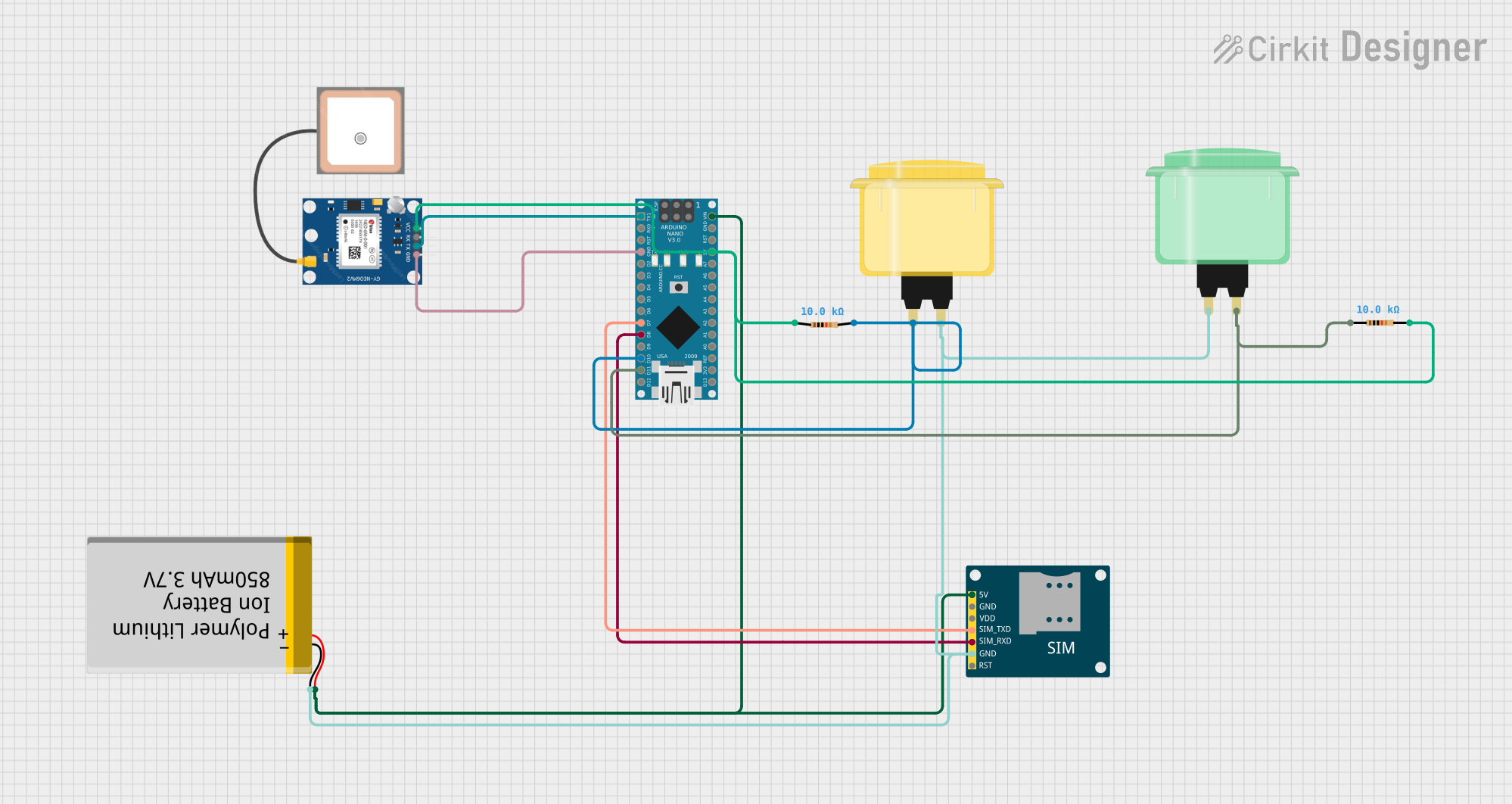
This circuit is designed to integrate a GPS module and a GSM module with an Arduino Nano microcontroller to enable location tracking and communication capabilities. The system can send an SMS with GPS coordinates and make a call when a button is pressed. It is powered by a Polymer Lithium Ion Battery and includes two arcade buttons for user interaction. The circuit also includes resistors for potential pull-up configurations on the buttons.
Component List
Arduino Nano
- Description: A compact microcontroller board based on the ATmega328P.
- Purpose: Acts as the central processing unit for the circuit, interfacing with the GPS and GSM modules, reading button states, and executing the embedded code.
GPS NEO 6M
- Description: A GPS module for satellite navigation.
- Purpose: Provides location data to the Arduino Nano.
SIM800L GSM Module
- Description: A GSM/GPRS module for cellular communication.
- Purpose: Enables the circuit to send SMS messages and make calls.
Arcade Button (Yellow)
- Description: A standard arcade-style pushbutton.
- Purpose: Triggers an action when pressed, such as sending an SMS with GPS coordinates.
Arcade Button (Green)
- Description: A standard arcade-style pushbutton.
- Purpose: Can be programmed to trigger different actions, potentially to initiate a call.
Polymer Lithium Ion Battery - 850mAh
- Description: A rechargeable battery providing power to the circuit.
- Purpose: Powers the entire circuit, ensuring portability and independence from external power sources.
Resistor (10k Ohms)
- Description: A resistor with a resistance of 10,000 Ohms.
- Purpose: Typically used for pull-up or pull-down configurations to ensure stable button operation.
Wiring Details
Arduino Nano
- D1/TX connected to GPS NEO 6M TX
- GND connected to GPS NEO 6M GND, SIM800L GSM Module GND, Arcade Button (Yellow), Arcade Button (Green), and Polymer Lithium Ion Battery GND
- D7 connected to SIM800L GSM Module SIM_TXD
- D8 connected to SIM800L GSM Module SIM_RXD
- D10 connected to Arcade Button (Yellow) through a 10k Ohm Resistor
- D11/MOSI connected to Arcade Button (Green) through a 10k Ohm Resistor
- VIN connected to Polymer Lithium Ion Battery VCC
- 5V connected to GPS NEO 6M VCC through a 10k Ohm Resistor
GPS NEO 6M
- VCC connected to Arduino Nano 5V through a 10k Ohm Resistor
- RX not connected
- TX connected to Arduino Nano D1/TX
- GND connected to Arduino Nano GND
SIM800L GSM Module
- 5V connected to Polymer Lithium Ion Battery VCC
- GND connected to Arduino Nano GND
- VDD not connected
- SIM_TXD connected to Arduino Nano D7
- SIM_RXD connected to Arduino Nano D8
- RST not connected
Arcade Button (Yellow)
- Pin connected to Arduino Nano D10 through a 10k Ohm Resistor
Arcade Button (Green)
- Pin connected to Arduino Nano D11/MOSI through a 10k Ohm Resistor
Polymer Lithium Ion Battery - 850mAh
- VCC connected to Arduino Nano VIN and SIM800L GSM Module 5V
- GND connected to Arduino Nano GND, SIM800L GSM Module GND, Arcade Button (Yellow), and Arcade Button (Green)
Resistor (10k Ohms)
- One end connected to Arcade Button (Yellow), the other end to Arduino Nano D10
- One end connected to Arcade Button (Green), the other end to Arduino Nano D11/MOSI
Documented Code
#include <TinyGPS.h>
#include <SoftwareSerial.h>
#include <Wire.h>

SoftwareSerial Gsm(6, 7); // GSM module connected to pin 6 (TX) and 7 (RX)
char phone_no[] = "+919819744611"; // Phone number to send SMS
TinyGPS gps; // GPS object
int state; // Button state
String textMessage; // Received text message

void setup() {
  Serial.begin(9600); // Start serial communication at 9600 baud rate
  Gsm.begin(9600); // Start GSM module communication at 9600 baud rate
  Serial.print("AT+CMGF=1\r"); // Set GSM module to SMS mode
  delay(100);
  Serial.print("AT+CNMI=2,2,0,0,0\r"); // New SMS message indications
  delay(100);
  pinMode(10, INPUT); // Set pin 10 as input for the yellow button
}

void loop() {
  bool newData = false;
  unsigned long chars;
  unsigned short sentences, failed;
  for (unsigned long start = millis(); millis() - start < 1000;) {
    while (Serial.available()) {
      char c = Serial.read();
      Serial.print(c);
      if (gps.encode(c)) // Encode GPS data
        newData = true;
    }
  }
  if (Gsm.available() > 0) {
    textMessage = Gsm.readString(); // Read SMS message
    textMessage.toUpperCase();
    delay(10);
  }
  state = digitalRead(10); // Read the state of the yellow button
  if (state == 0) {
    float flat, flon;
    unsigned long age;
    gps.f_get_position(&flat, &flon, &age); // Get GPS position
    Gsm.print("AT+CMGF=1\r");
    delay(400);
    Gsm.print("AT+CMGS=\""); // Start SMS message
    Gsm.print(phone_no);
    Gsm.println("\"");
    Gsm.println("Alert I need help............."); // SMS content
    Gsm.print("http://maps.google.com/maps?q=loc:"); // Google Maps link
    Gsm.print(flat == TinyGPS::GPS_INVALID_F_ANGLE ? 0.0 : flat, 6);
    Gsm.print(",");
    Gsm.print(flon == TinyGPS ::GPS_INVALID_F_ANGLE ? 0.0 : flon, 6);
    delay(200);
    Gsm.println((char)26); // End SMS message
    delay(200);
    Gsm.println();
    Serial.println("SMS Sent");

    Serial.println("Call"); // Start call
    delay(20000);
    Gsm.println("ATD+919869764653;"); // Dial number
    delay(150000);
    Gsm.println("ATH"); // Hang up
    delay(1000);
  } else {
    delay(10);
  }
  Serial.println(failed);
}
Note: The code provided is for the Arduino Nano microcontroller and includes functionality for reading GPS data, sending SMS messages, and making calls when the yellow arcade button is pressed. The GSM module is interfaced using the SoftwareSerial library, and the TinyGPS library is used to parse the GPS data. The code includes placeholders for phone numbers and should be customized with actual numbers before deployment.