Cirkit Designer
Your all-in-one circuit design IDE
Home /
Project Documentation
Arduino UNO Based Air Quality Monitor with GP2Y1010AU0F Dust Sensor

Circuit Documentation
Summary of the Circuit
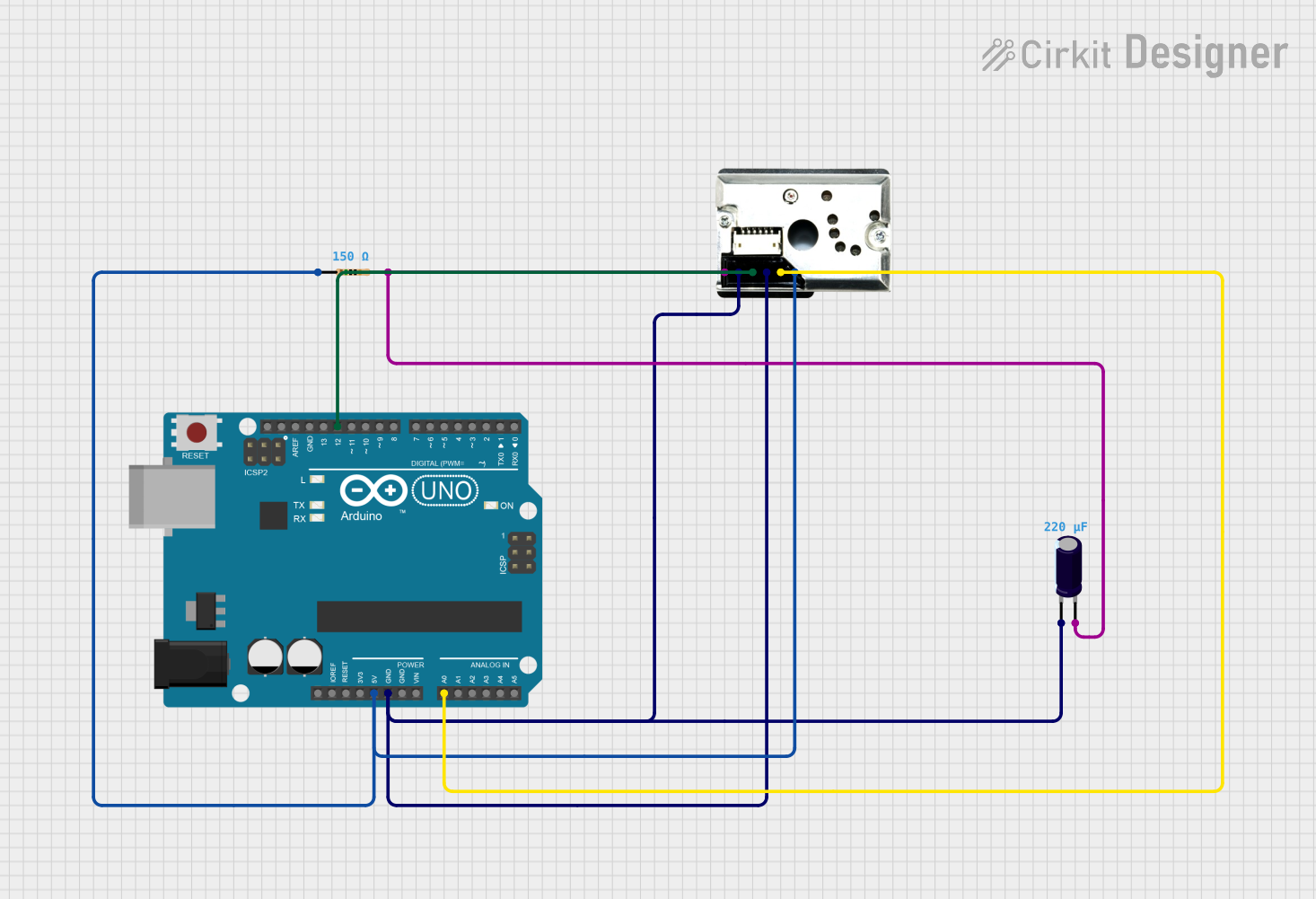
This circuit integrates an Arduino UNO microcontroller with a GP2Y1010AU0F dust sensor, a resistor, and an electrolytic capacitor. The Arduino UNO is used to control and read the output from the dust sensor. The resistor and capacitor are used to support the operation of the dust sensor, with the resistor acting as a current-limiting component for the sensor's LED and the capacitor stabilizing the LED power supply.
Component List
Electrolytic Capacitor
- Description: A capacitor used for filtering and stabilizing the power supply.
- Capacitance: 0.00022 Farads
GP2Y1010AU0F (Dust Sensor)
- Description: An optical air quality sensor designed to sense dust particles.
- Pins: VCC, Vout, S-GND, LED, LED-GND, V-LED
Arduino UNO (Microcontroller)
- Description: A microcontroller board based on the ATmega328P, widely used for building digital devices and interactive objects.
- Pins: UNUSED, IOREF, Reset, 3.3V, 5V, GND, Vin, A0-A5, SCL, SDA, AREF, D13-D0
Resistor
- Description: A passive two-terminal electrical component that implements electrical resistance as a circuit element.
- Resistance: 150 Ohms
Wiring Details
Electrolytic Capacitor
- Negative Pin (-): Connected to GND of Arduino UNO and S-GND, LED-GND of GP2Y1010AU0F.
- Positive Pin (+): Connected to V-LED of GP2Y1010AU0F and pin2 of the Resistor.
GP2Y1010AU0F (Dust Sensor)
- VCC: Connected to 5V of Arduino UNO and pin1 of the Resistor.
- Vout: Connected to A0 of Arduino UNO.
- S-GND & LED-GND: Connected to GND of Arduino UNO and Negative Pin (-) of Electrolytic Capacitor.
- LED: Connected to D12 of Arduino UNO.
- V-LED: Connected to Positive Pin (+) of Electrolytic Capacitor and pin2 of the Resistor.
Arduino UNO (Microcontroller)
- 5V: Connected to VCC of GP2Y1010AU0F and pin1 of the Resistor.
- GND: Connected to S-GND, LED-GND of GP2Y1010AU0F and Negative Pin (-) of Electrolytic Capacitor.
- A0: Connected to Vout of GP2Y1010AU0F.
- D12: Connected to LED of GP2Y1010AU0F.
Resistor
- Pin1: Connected to 5V of Arduino UNO and VCC of GP2Y1010AU0F.
- Pin2: Connected to V-LED of GP2Y1010AU0F and Positive Pin (+) of Electrolytic Capacitor.
Documented Code
Arduino UNO Code (sketch.ino)
void setup() {
  // put your setup code here, to run once:

}

void loop() {
  // put your main code here, to run repeatedly:

}
Note: The provided code is a template and does not contain any functional code specific to the operation of the circuit. It will need to be populated with the appropriate setup and loop code to control the GP2Y1010AU0F dust sensor and process its output.