
Solar-Powered Smart Control System with Arduino and Load Sensing
View and Edit Project In Cirkit Designer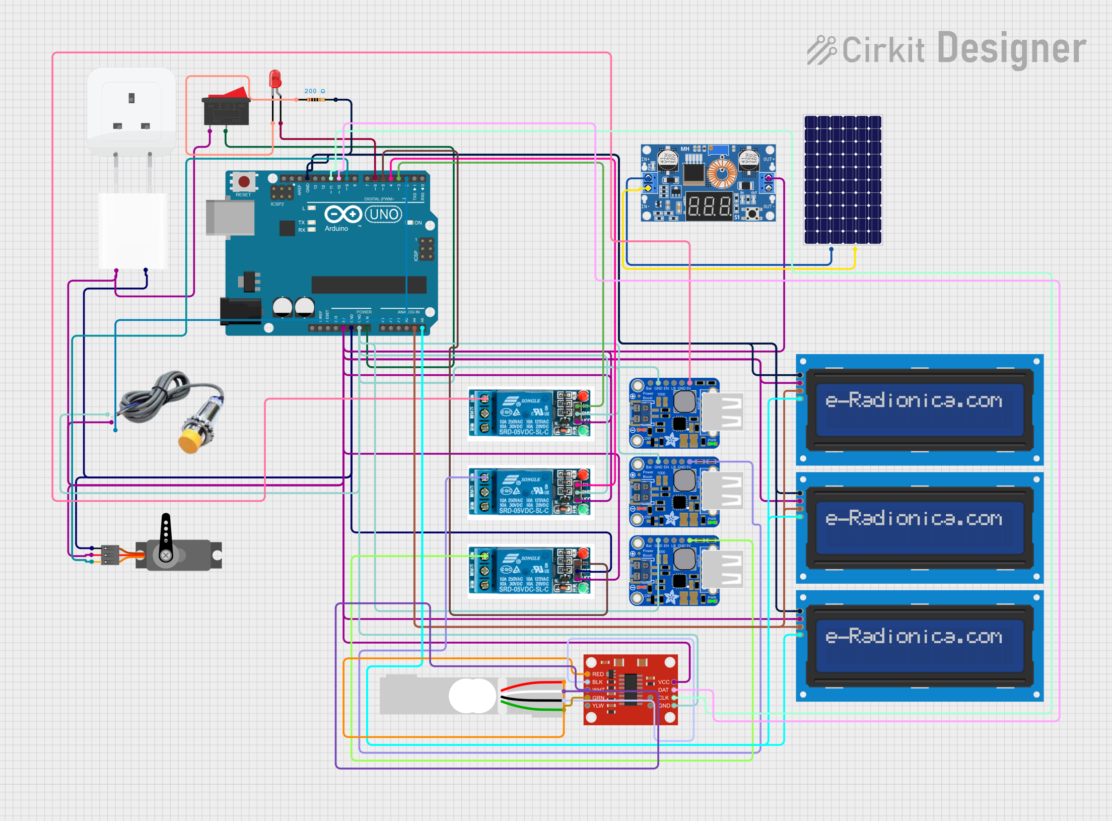
Circuit Documentation
Summary
This circuit is designed to interface various components including an Arduino UNO, a 5V Adapter, a solar panel, a DC-DC step-down converter, USB power boosters, relays, an LED, a resistor, capacitive sensor, servo motor, load cell with amplifier, and multiple LCD screens. The circuit appears to be a control system that can receive input from a capacitive sensor and a load cell, drive a servo, display information on LCD screens, and switch power to various components using relays. The power is supplied by a solar panel regulated by a DC-DC step-down converter and supplemented by a 5V adapter. The Arduino UNO serves as the central microcontroller unit to control the logic of the circuit.
Component List
Socket
- A standard electrical socket with earth, life, and neutral pins.
5V Adapter
- An adapter that converts AC to a 5V DC output.
Arduino UNO
- A microcontroller board based on the ATmega328P with various digital and analog I/O pins.
Solar Panel
- A photovoltaic panel that provides electrical power when exposed to sunlight.
XL4015 5A DC Buck Step-down Converter
- A DC-DC step-down (buck) converter capable of handling up to 5A of current.
PowerBoost 1000 Basic Terminal USB
- A USB power booster for providing a regulated 5V output from a battery.
5V Relay
- An electromechanical switch that allows control of a large current with a small current.
Rocker Switch
- A simple on/off switch to control the power flow.
LED: Two Pin (red)
- A basic red LED with an anode and cathode.
Resistor
- A 200 Ohm resistor used to limit current, possibly for the LED.
Capacitive Sensor
- A sensor that detects touch or proximity.
Servo
- A motor with feedback control for precise positioning.
LCD Screen 16x2 I2C
- A 16x2 character LCD display with an I2C interface.
Load Cell - Red/white/black/green
- A transducer that converts force into an electrical signal.
SparkFun Load Cell Amplifier - HX711
- An amplifier specifically designed to interface with a load cell.
Wiring Details
Arduino UNO
- 5V and GND pins are connected to the 5V and GND rails, respectively.
- Digital pins D2 to D11 are used for interfacing with the capacitive sensor, relays, servo, LED, and HX711 load cell amplifier.
- Analog pins A4 and A5 are connected to the SDA and SCL lines of the I2C bus for the LCD screens.
5V Adapter
- Provides 5V and GND to the circuit.
Solar Panel
- Connected to the input of the XL4015 DC-DC step-down converter.
XL4015 5A DC Buck Step-down Converter
- Steps down the voltage from the solar panel to a regulated output connected to the 5V rail.
PowerBoost 1000 Basic Terminal USB
- Multiple units are used, likely for providing 5V to the relays and as a backup power source.
5V Relay
- Controlled by the Arduino UNO to switch various loads in the circuit.
Rocker Switch
- Controls the Vin to the Arduino UNO, allowing the board to be powered on or off.
LED: Two Pin (red)
- Connected to a digital pin on the Arduino UNO through a 200 Ohm resistor.
Resistor
- Limits the current to the LED to prevent damage.
Capacitive Sensor
- Powered by the 5V rail and sends its signal to a digital pin on the Arduino UNO.
Servo
- Powered by the 5V rail and controlled by a PWM signal from the Arduino UNO.
LCD Screen 16x2 I2C
- All screens are connected to the I2C bus controlled by the Arduino UNO and share a common power and ground.
Load Cell and HX711 Amplifier
- The load cell is connected to the HX711 amplifier, which in turn is interfaced with the Arduino UNO for reading weight measurements.
Documented Code
Arduino UNO Sketch (sketch.ino)
void setup() {
  // put your setup code here, to run once:

}

void loop() {
  // put your main code here, to run repeatedly:

}
This code is a template and does not contain any functional code. It needs to be populated with the setup and loop functions to control the circuit's components based on the desired logic and functionality.