
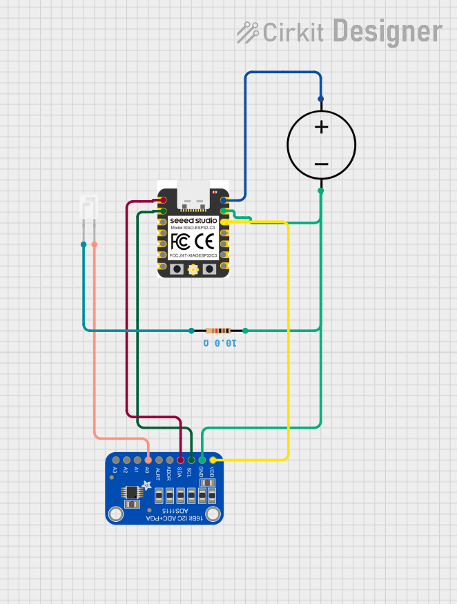
Circuit Documentation
Summary of the Circuit
This circuit is designed to read currents from four phototransistors using an Adafruit ADS1115 16-bit ADC, which is interfaced with a Xiao ESP32 C3 microcontroller via I2C communication. The ADC converts the analog signals from the phototransistors into digital values that the microcontroller can process. The readings are then printed to the Serial monitor. The circuit is powered by a DC power source, and a resistor is used to form a pull-down network for the phototransistor.
Component List
Xiao ESP32 C3
- Description: A microcontroller with WiFi and Bluetooth capabilities, equipped with digital I/O pins, power pins, and I2C communication pins.
- Pins: D7, D8, D9, D10, 3.3v, GND, VUSB, D6, D5, D4, D3, D2, D1, D0
Adafruit ADS1115 16Bit I2C ADC
- Description: A precision analog-to-digital converter (ADC) with 16-bit resolution, interfaced over an I2C bus.
- Pins: VDD, GND, SCL, SDA, ADDR, ALERT, AIN0, AIN1, AIN2, AIN3
DC Power Source
- Description: Provides the necessary power to the circuit.
- Pins: Ground, Positive
Phototransistor
- Description: A light-sensitive transistor that generates a current when exposed to light.
- Pins: C (Collector), E (Emitter)
Resistor (10 Ohms)
- Description: A passive component used to limit current or divide voltages.
- Pins: pin1, pin2
- Properties: Resistance: 10 Ohms
Wiring Details
Xiao ESP32 C3
- 3.3v connected to Adafruit ADS1115 VDD
- GND connected to Resistor pin1, DC Power Source Ground, and Adafruit ADS1115 GND
- VUSB connected to DC Power Source Positive
- D1 connected to Adafruit ADS1115 SCL
- D0 connected to Adafruit ADS1115 SDA
Adafruit ADS1115 16Bit I2C ADC
- VDD connected to Xiao ESP32 C3 3.3v
- GND connected to Xiao ESP32 C3 GND
- SCL connected to Xiao ESP32 C3 D1
- SDA connected to Xiao ESP32 C3 D0
- AIN0 connected to Phototransistor C
DC Power Source
- Ground connected to Xiao ESP32 C3 GND
- Positive connected to Xiao ESP32 C3 VUSB
Phototransistor
- C connected to Adafruit ADS1115 AIN0
- E connected to Resistor pin2
Resistor (10 Ohms)
- pin1 connected to Xiao ESP32 C3 GND
- pin2 connected to Phototransistor E
Documented Code
/*
 * This Arduino Sketch reads the currents from four phototransistors using
 * an Adafruit ADS1115 16-bit ADC connected via I2C to a Xiao ESP32 C3.
 * The readings are printed to the Serial monitor.
 */

#include <Wire.h>
#include <Adafruit_ADS1X15.h>

Adafruit_ADS1115 ads;  // Create an ADS1115 object

void setup() {
  Serial.begin(115200);  // Initialize serial communication
  Wire.begin();  // Initialize I2C communication
  ads.begin();  // Initialize the ADS1115
}

void loop() {
  int16_t adc0, adc1, adc2, adc3;
  adc0 = ads.readADC_SingleEnded(0);  // Read AIN0
  adc1 = ads.readADC_SingleEnded(1);  // Read AIN1
  adc2 = ads.readADC_SingleEnded(2);  // Read AIN2
  adc3 = ads.readADC_SingleEnded(3);  // Read AIN3

  // Print data to Serial monitor
  Serial.print("AIN0: ");
  Serial.print(adc0);
  Serial.print("\tAIN1: ");
  Serial.print(adc1);
  Serial.print("\tAIN2: ");
  Serial.print(adc2);
  Serial.print("\tAIN3: ");
  Serial.println(adc3);

  delay(1000);  // Wait for 1 second before next reading
}
The code is written for the Arduino platform and is intended to be uploaded to the Xiao ESP32 C3 microcontroller. It initializes the I2C communication, sets up the ADS1115 ADC, and continuously reads the analog inputs from the phototransistors, printing the results to the Serial monitor every second.