Light-Activated Piezo Speaker with Manual Power Switch
Circuit Documentation
Summary of the Circuit
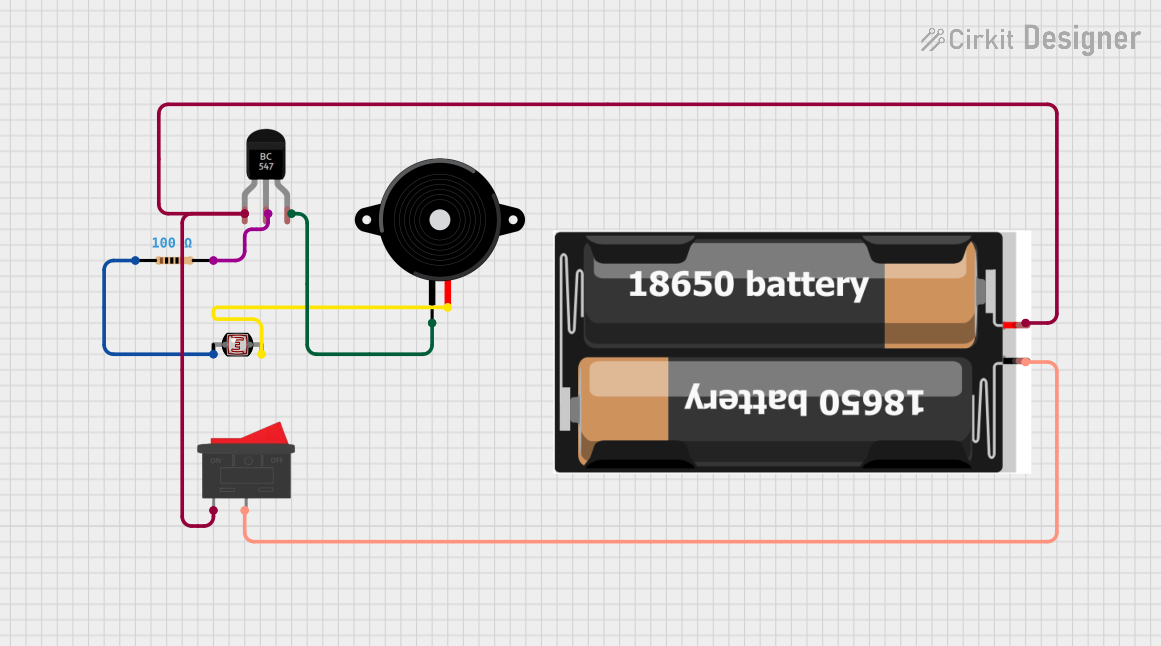
This circuit appears to be a simple light-activated switch using a BC547 transistor as a control element. The circuit is powered by a 2x 18650 battery pack and includes a photocell (LDR) to sense the light level, a resistor to limit current, and a piezo speaker as an output device. A rocker switch is used to turn the circuit on and off. When the light level changes, the resistance of the LDR changes, which in turn affects the base current of the transistor. This causes the transistor to switch states, activating the piezo speaker.
Component List
BC547 Transistor
- Description: A general-purpose NPN bipolar junction transistor (BJT) used for switching and amplification.
- Pins: Collector, Base, Emitter
Resistor
- Description: A passive two-terminal electrical component that implements electrical resistance as a circuit element.
- Value: 100 Ohms
Photocell (LDR)
- Description: A light-dependent resistor whose resistance decreases with increasing incident light intensity.
- Pins: pin 0, pin 1
Piezo Speaker
- Description: An electronic device that emits sound when an electric signal is applied across its pins.
- Pins: pin1, pin2
2x 18650 Battery Pack
- Description: A power source consisting of two 18650 batteries.
- Pins: vcc, gnd
Rocker Switch
- Description: A switch that rocks back and forth to open or close the circuit.
- Pins: 1, 2
Wiring Details
BC547 Transistor
- Collector: Connected to the Rocker Switch and the 2x 18650 battery pack (vcc).
- Base: Connected to the Resistor (pin2).
- Emitter: Connected to the Piezo Speaker (pin1).
Resistor
- pin1: Connected to the Photocell (LDR) (pin 0).
- pin2: Connected to the BC547 Transistor (Base).
Photocell (LDR)
- pin 0: Connected to the Resistor (pin1).
- pin 1: Connected to the Piezo Speaker (pin2).
Piezo Speaker
- pin1: Connected to the BC547 Transistor (Emitter).
- pin2: Connected to the Photocell (LDR) (pin 1).
2x 18650 Battery Pack
- vcc: Connected to the Rocker Switch (1) and the BC547 Transistor (Collector).
- gnd: Connected to the Rocker Switch (2).
Rocker Switch
- 1: Connected to the 2x 18650 battery pack (vcc) and the BC547 Transistor (Collector).
- 2: Connected to the 2x 18650 battery pack (gnd).
Documented Code
There is no microcontroller code provided for this circuit. If the circuit is intended to be controlled by a microcontroller, the code would be necessary to define the behavior of the microcontroller in response to the input from the LDR and to control the output to the Piezo Speaker. Since no code is provided, it is assumed that the circuit operates purely in an analog fashion based on the components listed and their wiring.