
NodeMCU and Arduino UNO Based Weather Monitoring System with LoRa Communication
View and Edit Project In Cirkit Designer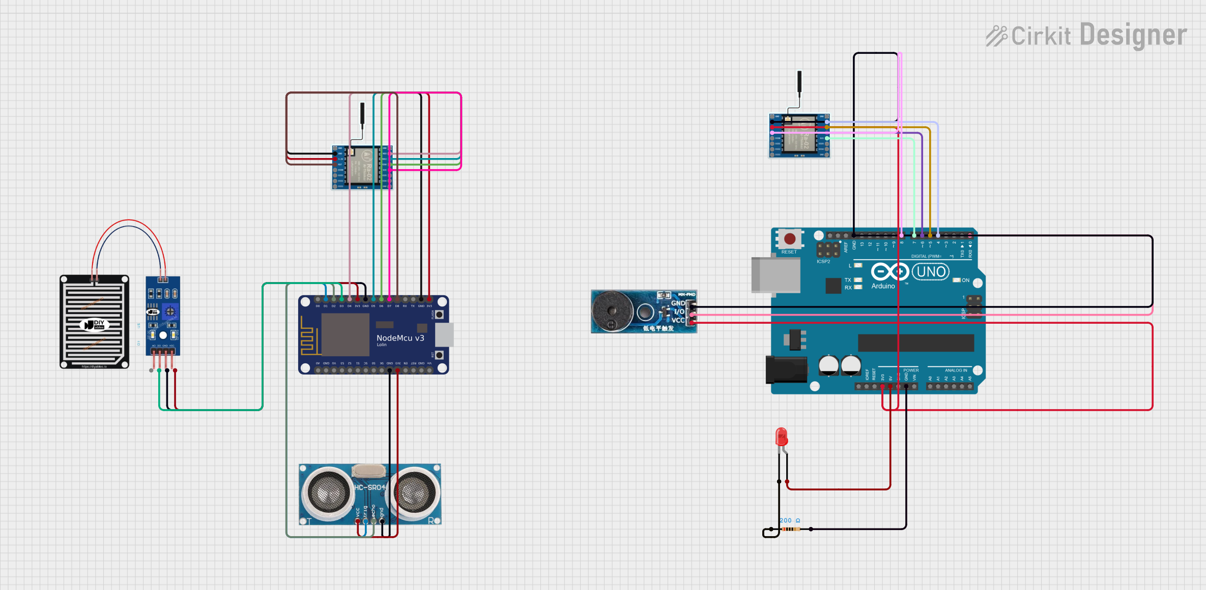
Circuit Documentation
Summary
This document provides a detailed overview of a circuit that integrates various sensors, a microcontroller, and communication modules. The circuit includes a NodeMCU V3 ESP8266, an Arduino UNO, an ultrasonic sensor, a rain sensor, a LoRa module, an LED, a buzzer module, and a resistor. The NodeMCU V3 ESP8266 is used to interface with the sensors and the LoRa module, while the Arduino UNO is used to control the LED and the buzzer module.
Component List
NodeMCU V3 ESP8266
- Description: A microcontroller with built-in Wi-Fi capabilities.
- Pins: A0, GND, VU, S3, S2, S1, SC, S0, SK, 3V3, EN, RST, Vin, D0, D1, D2, D3, D4, D5, D6, D7, D8, RX, TX
RAIN SENSOR
- Description: A sensor used to detect rain.
- Pins: AO, DO, GRD, VCC
Ultrasonic Sensor
- Description: A sensor used to measure distance using ultrasonic waves.
- Pins: +VCC, Trigger, Echo, GND
LoRa Ra-02 SX1278
- Description: A long-range, low-power wireless communication module.
- Pins: GND, NSS, MOSI, MISO, SCK, D105, DI04, 3.3V, RST, DI00, DI01, D102, DI03
Arduino UNO
- Description: A microcontroller board based on the ATmega328P.
- Pins: UNUSED, IOREF, Reset, 3.3V, 5V, GND, Vin, A0, A1, A2, A3, A4, A5, SCL, SDA, AREF, D13, D12, D11, D10, D9, D8, D7, D6, D5, D4, D3, D2, D1, D0
LED: Two Pin (red)
- Description: A red LED with two pins.
- Pins: cathode, anode
Buzzer Module
- Description: A module used to produce sound.
- Pins: GND, Vcc, I/O
Resistor
- Description: A 200 Ohm resistor.
- Pins: pin1, pin2
- Properties: Resistance: 200 Ohms
Wiring Details
NodeMCU V3 ESP8266
- GND connected to Ultrasonic Sensor GND
- 3V3 connected to Ultrasonic Sensor +VCC
- D1 connected to Ultrasonic Sensor Trigger
- D2 connected to Ultrasonic Sensor Echo
- D3 connected to RAIN SENSOR DO
- D4 connected to LoRa Ra-02 SX1278 NSS
- 3V3 connected to RAIN SENSOR VCC
- GND connected to RAIN SENSOR GRD
- D5 connected to LoRa Ra-02 SX1278 MOSI
- D6 connected to LoRa Ra-02 SX1278 MISO
- D7 connected to LoRa Ra-02 SX1278 SCK
- D8 connected to LoRa Ra-02 SX1278 RST
- GND connected to LoRa Ra-02 SX1278 GND
- 3V3 connected to LoRa Ra-02 SX1278 3.3V
RAIN SENSOR
- DO connected to NodeMCU V3 ESP8266 D3
- VCC connected to NodeMCU V3 ESP8266 3V3
- GRD connected to NodeMCU V3 ESP8266 GND
Ultrasonic Sensor
- GND connected to NodeMCU V3 ESP8266 GND
- +VCC connected to NodeMCU V3 ESP8266 3V3
- Trigger connected to NodeMCU V3 ESP8266 D1
- Echo connected to NodeMCU V3 ESP8266 D2
LoRa Ra-02 SX1278
- NSS connected to NodeMCU V3 ESP8266 D4
- MOSI connected to NodeMCU V3 ESP8266 D5
- MISO connected to NodeMCU V3 ESP8266 D6
- SCK connected to NodeMCU V3 ESP8266 D7
- RST connected to NodeMCU V3 ESP8266 D8
- GND connected to NodeMCU V3 ESP8266 GND
- 3.3V connected to NodeMCU V3 ESP8266 3V3
Arduino UNO
- 3.3V connected to LoRa Ra-02 SX1278 3.3V and Buzzer Module Vcc
- 5V connected to LED: Two Pin (red) anode
- GND connected to Resistor pin2, LoRa Ra-02 SX1278 GND, and Buzzer Module GND
- D8 connected to LoRa Ra-02 SX1278 RST
- D7 connected to LoRa Ra-02 SX1278 SCK
- D6 connected to LoRa Ra-02 SX1278 MISO
- D5 connected to LoRa Ra-02 SX1278 MOSI
- D4 connected to LoRa Ra-02 SX1278 NSS
- D0 connected to Buzzer Module I/O
LED: Two Pin (red)
- anode connected to Arduino UNO 5V
- cathode connected to Resistor pin1
Buzzer Module
- Vcc connected to Arduino UNO 3.3V
- GND connected to Arduino UNO GND
- I/O connected to Arduino UNO D0
Resistor
- pin1 connected to LED: Two Pin (red) cathode
- pin2 connected to Arduino UNO GND
Documented Code
Arduino UNO Code
void setup() {
  // put your setup code here, to run once:

}

void loop() {
  // put your main code here, to run repeatedly:

}
This code is a basic template for the Arduino UNO. The setup function is used to initialize any settings or configurations, and the loop function contains the main code that runs repeatedly.