
Solar-Powered Automated Irrigation System with Water Level Monitoring
View and Edit Project In Cirkit Designer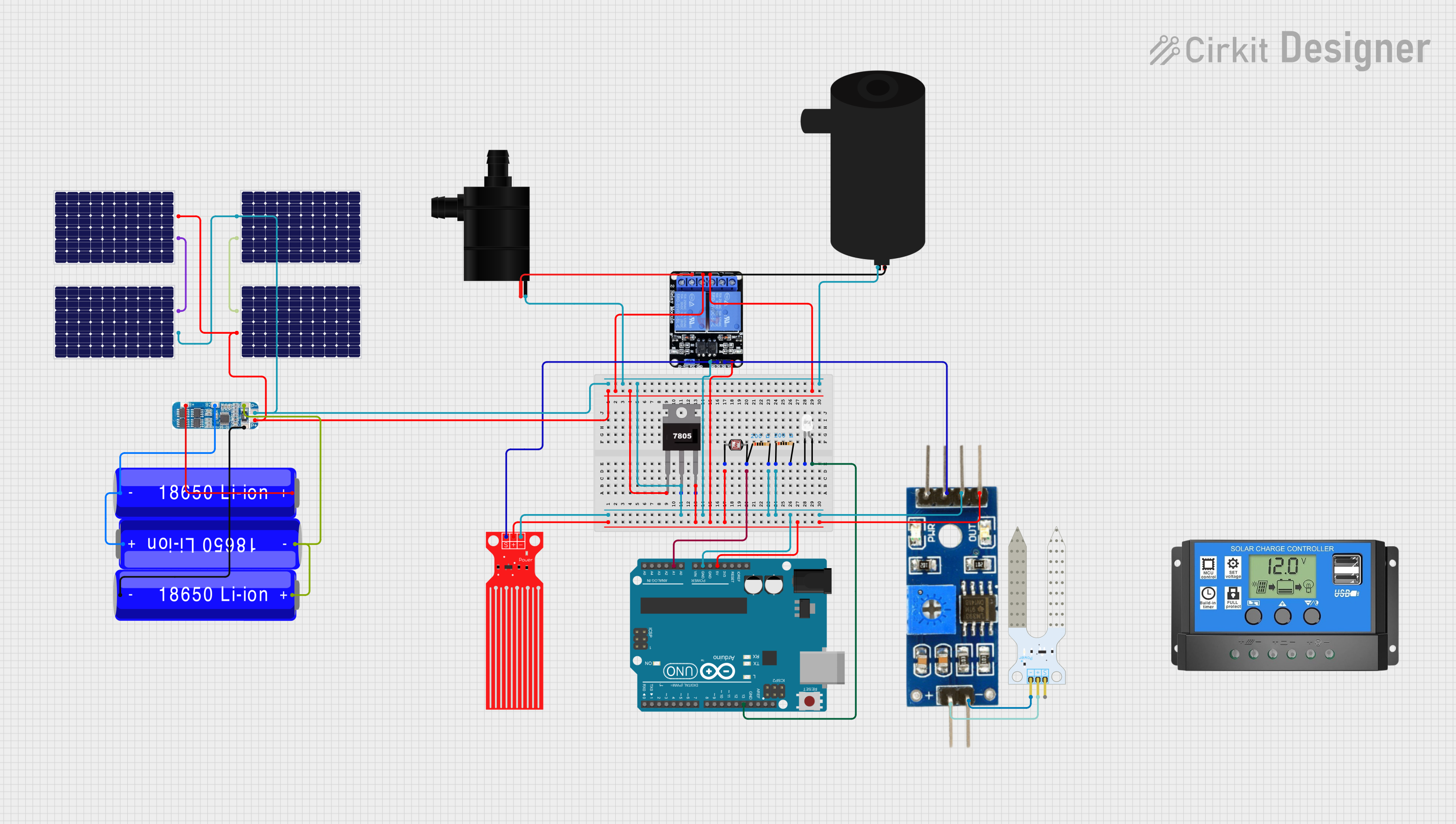
Circuit Documentation
Summary of the Circuit
This circuit appears to be designed for monitoring and controlling environmental conditions, possibly for applications like automated gardening or water level management. It includes sensors for detecting soil moisture and water levels, a relay for controlling power to pumps, a voltage regulator, an Arduino UNO microcontroller for processing sensor data and controlling the relay, and a power management system with solar panels and batteries.
Component List
Two Channel Relay 5v
- Description: A relay module with two channels that can control high power devices.
- Pins: VCC, IN2, IN1, GND, NC2, C2, NO2, NC1, C1, NO1
Water Level Sensor
- Description: A sensor for detecting the level of water.
- Pins: SIG, VCC, GND
Water Pump
- Description: A device used to move water from one place to another.
- Pins: VCC, GND
7805 Voltage Regulator
- Description: A voltage regulator that outputs a stable 5V from a higher voltage input.
- Pins: Vin, Gnd, Vout
Arduino UNO
- Description: A microcontroller board based on the ATmega328P.
- Pins: UNUSED, IOREF, Reset, 3.3V, 5V, GND, Vin, A0-A5, SCL, SDA, AREF, D0-D13
LED: Two Pin (white)
- Description: A white light-emitting diode.
- Pins: cathode, anode
Resistor (200 Ohms)
- Description: A resistor with a resistance of 200 Ohms.
- Pins: pin1, pin2
Photocell (LDR)
- Description: A light-dependent resistor whose resistance changes with light intensity.
- Pins: pin 0, pin 1
Soil Moisture Module
- Description: A module for detecting the moisture content in soil.
- Pins: positive, negative, Analog, Digital, Ground, VCC
Soil Moisture Sensor
- Description: A sensor for measuring the moisture content in soil.
- Pins: VCC, GND, SIG
Solar Panel
- Description: A panel that converts solar energy into electrical energy.
- Pins: +, -
18650 Li-ion Battery
- Description: A rechargeable lithium-ion battery.
- Pins: -, +
BMS (Battery Management System)
- Description: A system for managing a rechargeable battery, ensuring safe charging and discharging.
- Pins: B+, B2, B1, B-, P-, P+
Solar Charge Controller
- Description: A device that controls the charging of batteries from solar panels.
- Pins: Solar Cell +, Solar Cell -, Battery +, Battery -, Load +, Load -
Wiring Details
Two Channel Relay 5v
- VCC: Connected to 5V power supply from the 7805 voltage regulator.
- IN2: Connected to the Digital pin of the Soil Moisture Module.
- IN1: Connected to the SIG pin of the Water Level Sensor.
- GND: Common ground.
- C2: Connected to the positive pin of the water pump.
- NO2, NC1: Not connected in this circuit.
Water Level Sensor
- SIG: Connected to IN1 of the Two Channel Relay.
- VCC: Connected to 5V power supply from the 7805 voltage regulator.
- GND: Common ground.
Water Pump
- VCC: Connected to C1 of the Two Channel Relay.
- GND: Common ground.
7805 Voltage Regulator
- Vin: Connected to the solar panel output.
- Gnd: Common ground.
- Vout: Provides 5V power supply to various components.
Arduino UNO
- 5V: Provides power to various components.
- GND: Common ground.
- A1: Connected to pin 1 of the Photocell (LDR).
- D13: Connected to the anode of the LED.
LED: Two Pin (white)
- anode: Connected to D13 on the Arduino UNO.
- cathode: Connected to ground through a 200 Ohm resistor.
Resistor (200 Ohms)
- pin1: Connected to the cathode of the LED.
- pin2: Common ground.
Photocell (LDR)
- pin 0: Connected to 5V power supply.
- pin 1: Connected to A1 on the Arduino UNO.
Soil Moisture Module
- VCC: Connected to 5V power supply.
- Ground: Common ground.
- Digital: Connected to IN2 of the Two Channel Relay.
Soil Moisture Sensor
- VCC: Connected to the positive pin of the Soil Moisture Module.
- GND: Connected to the negative pin of the Soil Moisture Module.
- SIG: Not connected in this circuit.
Solar Panel
- +: Connected to the Solar Charge Controller.
- -: Connected to the common ground and to the Solar Charge Controller.
18650 Li-ion Battery
- +: Connected to the BMS.
- -: Connected to the BMS and common ground.
BMS (Battery Management System)
- B+, B2, B1, B-: Connected to the corresponding battery terminals.
- P-: Common ground.
- P+: Connected to the NO2 of the Two Channel Relay.
Solar Charge Controller
- Solar Cell +, Solar Cell -: Connected to the solar panels.
- Battery +, Battery -: Connected to the BMS.
- Load +, Load -: Not connected in this circuit.
Documented Code
Arduino UNO (sketch.ino)
void setup() {
  // put your setup code here, to run once:

}

void loop() {
  // put your main code here, to run repeatedly:

}
Additional Notes
- The provided code is a template and does not contain any functional code specific to the circuit's operation.
- Further development of the code is required to read sensor data, control the relay, and manage the power system.
- The code should include logic for reading the water level and soil moisture sensors, and based on their readings, control the water pumps through the relay.
- Additional code may be needed to manage power from the solar panels and batteries, ensuring efficient energy usage and battery health.