Arduino UNO-Based Motion and Flex Sensor System with Bluetooth Connectivity
Circuit Documentation
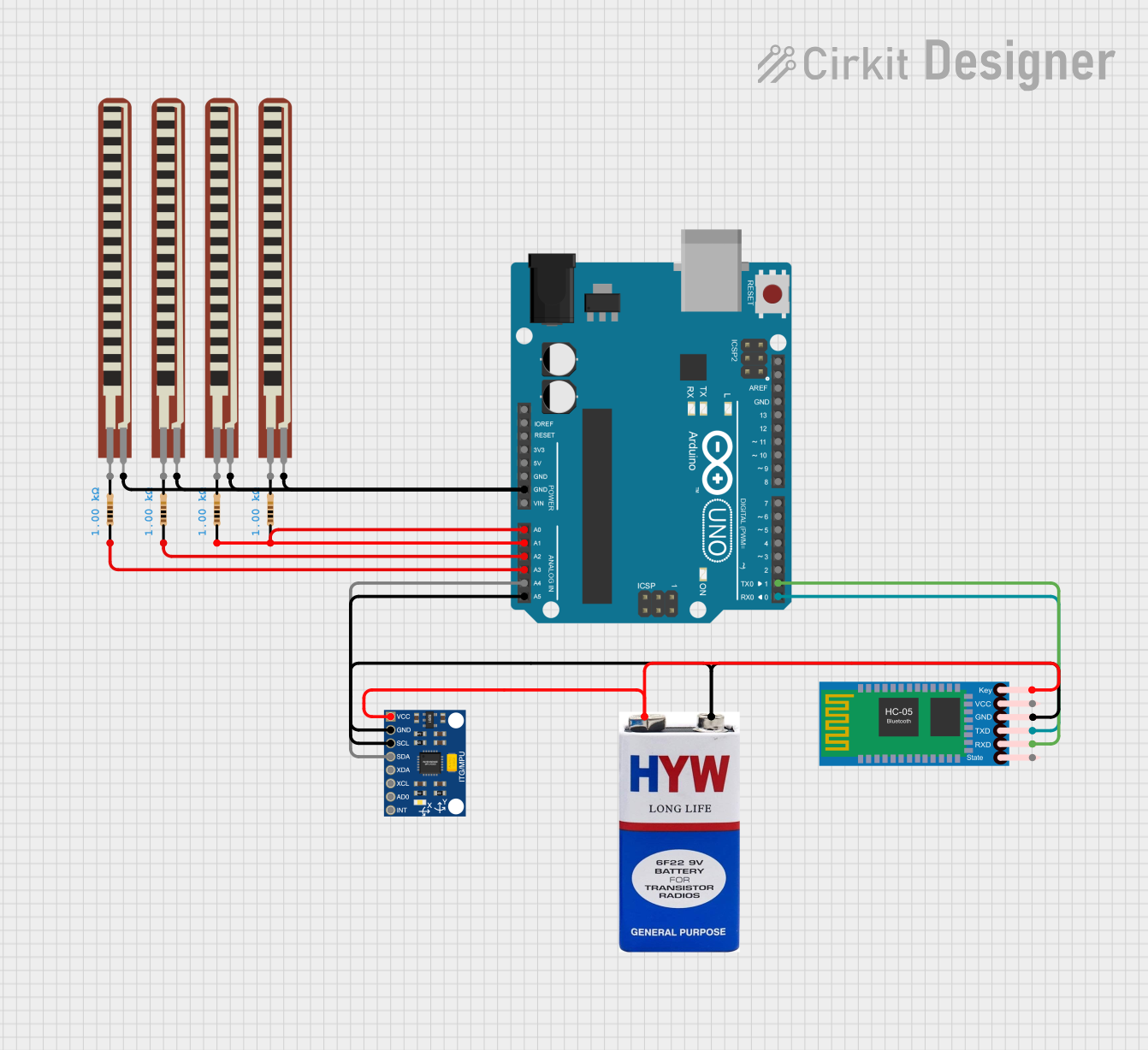
Summary
This circuit involves an Arduino UNO microcontroller interfacing with an MPU6050 accelerometer and gyroscope sensor, an HC-05 Bluetooth module, several flex resistors, and standard resistors. The circuit is powered by a 9V battery. The Arduino UNO reads data from the MPU6050 and flex resistors, and communicates with the HC-05 Bluetooth module to transmit data wirelessly.
Component List
Arduino UNO
- Description: A microcontroller board based on the ATmega328P.
- Pins: UNUSED, IOREF, Reset, 3.3V, 5V, GND, Vin, A0, A1, A2, A3, A4, A5, SCL, SDA, AREF, D13, D12, D11, D10, D9, D8, D7, D6, D5, D4, D3, D2, D1, D0
InvenSense MPU6050
- Description: A 6-axis motion tracking device that combines a 3-axis gyroscope and a 3-axis accelerometer.
- Pins: VCC, GND, SCL, SDA, XDA, XCL, AD0, INT
HC-05 Bluetooth Module
- Description: A Bluetooth module for wireless communication.
- Pins: Key, VCC, TXD, RXD, State, GND
2.2 inch Basic Flex Resistor
- Description: A flex sensor that changes resistance when bent.
- Pins: Pin 2, pin 1
Resistor (1000 Ohms)
- Description: A standard resistor with a resistance of 1000 Ohms.
- Pins: pin1, pin2
9V Battery
- Description: A standard 9V battery for powering the circuit.
- Pins: +, -
Wiring Details
Arduino UNO
GND is connected to:
- Pin 1 of all 2.2 inch Basic Flex Resistors
A0 is connected to:
- pin1 of a 1000 Ohm Resistor
A1 is connected to:
- pin1 of a 1000 Ohm Resistor
A2 is connected to:
- pin1 of a 1000 Ohm Resistor
A3 is connected to:
- pin1 of a 1000 Ohm Resistor
A4 is connected to:
- SDA of the InvenSense MPU6050
A5 is connected to:
- SCL of the InvenSense MPU6050
D1 is connected to:
- RXD of the HC-05 Bluetooth Module
D0 is connected to:
- TXD of the HC-05 Bluetooth Module
InvenSense MPU6050
VCC is connected to:
- Key of the HC-05 Bluetooth Module
- of the 9V Battery
GND is connected to:
- GND of the HC-05 Bluetooth Module
- of the 9V Battery
HC-05 Bluetooth Module
Key is connected to:
- VCC of the InvenSense MPU6050
- of the 9V Battery
GND is connected to:
- GND of the InvenSense MPU6050
- of the 9V Battery
2.2 inch Basic Flex Resistor
- Pin 1 is connected to:
- GND of the Arduino UNO
Resistor (1000 Ohms)
pin1 of one resistor is connected to:
- A0 of the Arduino UNO
pin1 of another resistor is connected to:
- A1 of the Arduino UNO
pin1 of another resistor is connected to:
- A2 of the Arduino UNO
pin1 of another resistor is connected to:
- A3 of the Arduino UNO
Documented Code
Arduino UNO Code (sketch.ino)
void setup() {
  // put your setup code here, to run once:

}

void loop() {
  // put your main code here, to run repeatedly:

}
Additional Documentation (documentation.txt)
This documentation provides a comprehensive overview of the circuit, including a summary, detailed component list, wiring details, and the code used in the microcontroller.