
Arduino UNO and 555 Timer-Based OLED Display Controller with Adjustable Timing
View and Edit Project In Cirkit Designer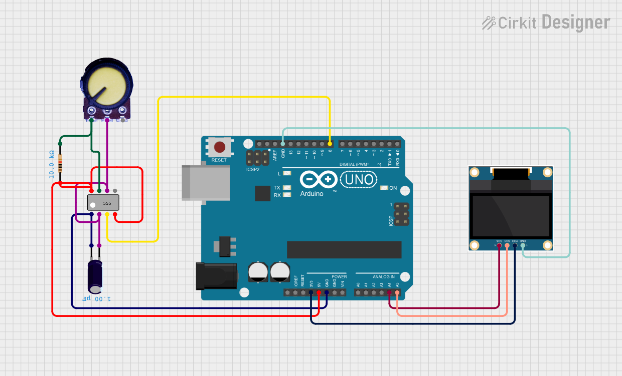
Circuit Documentation
Summary
This document provides a detailed overview of a circuit that includes an Arduino UNO, a 555 timer IC, a 0.96" OLED display, a potentiometer, a resistor, and an electrolytic capacitor. The circuit is designed to interface the Arduino with the OLED display and the 555 timer, with additional components to support the functionality.
Component List
Arduino UNO
- Description: A microcontroller board based on the ATmega328P.
- Pins: UNUSED, IOREF, Reset, 3.3V, 5V, GND, Vin, A0, A1, A2, A3, A4, A5, SCL, SDA, AREF, D13, D12, D11, D10, D9, D8, D7, D6, D5, D4, D3, D2, D1, D0
555 Timer IC
- Description: A highly stable device for generating accurate time delays or oscillation.
- Pins: GND, TRIG, OUT, ~RESET, VCC, DIS, THR, CTRL
0.96" OLED Display
- Description: A small OLED display module.
- Pins: GND, VDD, SCK, SDA
Potentiometer
- Description: A variable resistor used to adjust levels.
- Pins: GND, Output, VCC
Resistor
- Description: A 10k Ohm resistor.
- Pins: pin1, pin2
- Properties:
- Resistance: 10k Ohms
Electrolytic Capacitor
- Description: A capacitor with a capacitance of 1 µF.
- Pins: -, +
- Properties:
- Capacitance: 1 µF
Wiring Details
Arduino UNO
- 3.3V connected to VDD of the 0.96" OLED Display.
- 5V connected to pin1 of the Resistor and ~RESET and VCC of the 555 Timer IC.
- GND connected to + of the Electrolytic Capacitor, GND of the 0.96" OLED Display, and GND of the 555 Timer IC.
- A4 connected to SDA of the 0.96" OLED Display.
- A5 connected to SCK of the 0.96" OLED Display.
- D8 connected to OUT of the 555 Timer IC.
555 Timer IC
- ~RESET connected to 5V of the Arduino UNO.
- VCC connected to 5V of the Arduino UNO.
- GND connected to + of the Electrolytic Capacitor and GND of the Arduino UNO.
- OUT connected to D8 of the Arduino UNO.
- TRIG connected to Output of the Potentiometer.
- THR connected to Output of the Potentiometer.
- DIS connected to pin2 of the Resistor.
0.96" OLED Display
- VDD connected to 3.3V of the Arduino UNO.
- GND connected to GND of the Arduino UNO.
- SCK connected to A5 of the Arduino UNO.
- SDA connected to A4 of the Arduino UNO.
Potentiometer
- Output connected to - of the Electrolytic Capacitor, TRIG and THR of the 555 Timer IC.
- GND connected to pin2 of the Resistor.
Resistor
- pin1 connected to 5V of the Arduino UNO.
- pin2 connected to GND of the Potentiometer and DIS of the 555 Timer IC.
Electrolytic Capacitor
- + connected to GND of the Arduino UNO and GND of the 555 Timer IC.
- - connected to Output of the Potentiometer.
Code Documentation
Arduino UNO Code
void setup() {
  // put your setup code here, to run once:

}

void loop() {
  // put your main code here, to run repeatedly:

}
This code is a basic template for the Arduino UNO. The setup() function is where you initialize your components and settings, and the loop() function is where the main logic of your program runs repeatedly.
Additional Documentation
The additional documentation file is empty and can be used to add further details or notes about the circuit and its operation.