Arduino UNO-Based Security System with Fingerprint Authentication and Servo Lock Control
Circuit Documentation
Summary
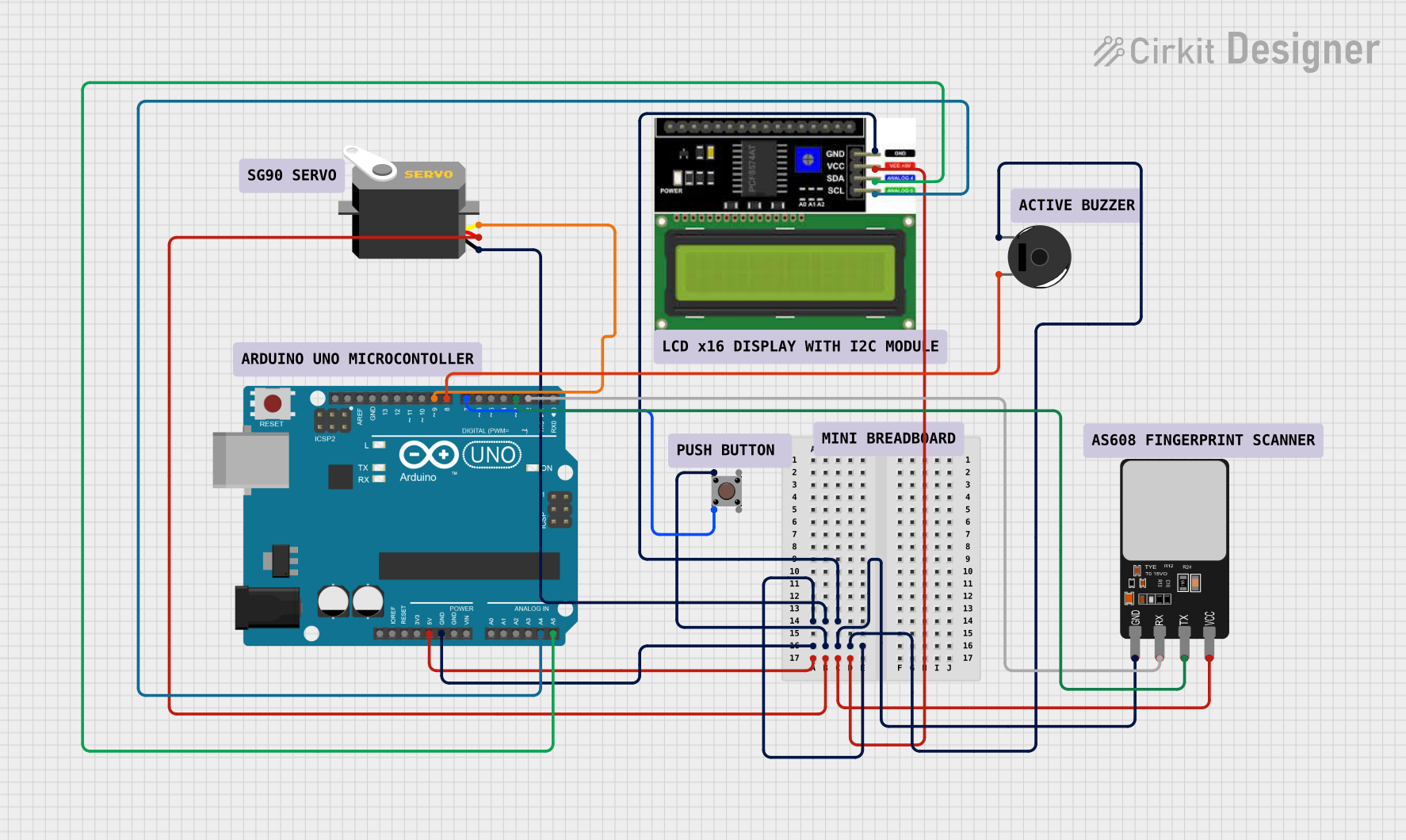
This circuit integrates various components controlled by an Arduino UNO microcontroller. The components include a Servo motor, a Pushbutton, a Piezo Buzzer, a Fingerprint Scanner, and an LCD I2C Display. The Arduino UNO manages input from the Pushbutton and the Fingerprint Scanner, controls the Servo motor and the Piezo Buzzer, and communicates with the LCD I2C Display via the I2C protocol. The circuit is designed to perform tasks that likely involve user interaction, identification via the fingerprint scanner, and feedback through auditory signals (buzzer) and visual display (LCD).
Component List
Arduino UNO
- Microcontroller board based on the ATmega328P
- It has 14 digital input/output pins, 6 analog inputs, a 16 MHz quartz crystal, a USB connection, a power jack, an ICSP header, and a reset button.
Servo
- A rotary actuator or linear actuator that allows for precise control of angular or linear position, velocity, and acceleration.
- It consists of a suitable motor coupled to a sensor for position feedback.
Pushbutton
- A simple switch mechanism for controlling some aspect of a machine or a process.
- Buttons are typically made out of hard material, usually plastic or metal.
Piezo Buzzer
- An electronic device commonly used to produce sound.
- The buzzer is used in alarm devices, timers, and confirmation of user input such as a mouse click or keystroke.
Fingerprint Scanner
- An electronic device used to capture a digital image of the fingerprint pattern.
- The captured image is called a live scan, which is digitally processed to create a biometric template.
LCD I2C Display
- A liquid crystal display that uses the I2C bus for communication.
- This display has an integrated I2C interface, which simplifies the connections with the microcontroller.
Wiring Details
Arduino UNO
- GND connected to the ground pins of the Fingerprint Scanner, Pushbutton, Servo, LCD I2C Display, and Piezo Buzzer.
- 5V supplies power to the VCC pins of the Fingerprint Scanner, Servo, and LCD I2C Display.
- A4 (SCL) connected to the SCL pin of the LCD I2C Display for I2C communication.
- A5 (SDA) connected to the SDA pin of the LCD I2C Display for I2C communication.
- D9 connected to the pulse pin of the Servo for control signals.
- D8 connected to pin 2 of the Piezo Buzzer for sound generation.
- D7 connected to Pin 2 (in) of the Pushbutton to detect button presses.
- D3 connected to the TX pin of the Fingerprint Scanner for serial communication.
- D2 connected to the RX pin of the Fingerprint Scanner for serial communication.
Servo
- gnd connected to the Arduino UNO GND.
- vcc connected to the Arduino UNO 5V.
- pulse connected to the Arduino UNO D9.
Pushbutton
- Pin 1 (in) connected to the Arduino UNO GND.
- Pin 2 (in) connected to the Arduino UNO D7.
Piezo Buzzer
- pin 1 connected to the Arduino UNO GND.
- pin 2 connected to the Arduino UNO D8.
Fingerprint Scanner
- GND connected to the Arduino UNO GND.
- VCC connected to the Arduino UNO 5V.
- TX connected to the Arduino UNO D3.
- RX connected to the Arduino UNO D2.
LCD I2C Display
- GND connected to the Arduino UNO GND.
- VCC connected to the Arduino UNO 5V.
- SDA connected to the Arduino UNO A5.
- SCL connected to the Arduino UNO A4.
Documented Code
void setup() {
  // put your setup code here, to run once:

}

void loop() {
  // put your main code here, to run repeatedly:

}
The provided code is a template for the Arduino UNO microcontroller. The setup() function is called once when the microcontroller is first powered on or reset. It is used to initialize the digital pins as input or output and to set up any other initial conditions. The loop() function is called repeatedly and contains the main logic of the program. It is where the microcontroller reads sensors, controls actuators, and performs other tasks. The actual implementation details need to be filled in based on the specific requirements of the circuit's operation.