
Arduino UNO-Based Coin-Operated Communication System with LCD Display and Servo Control
View and Edit Project In Cirkit Designer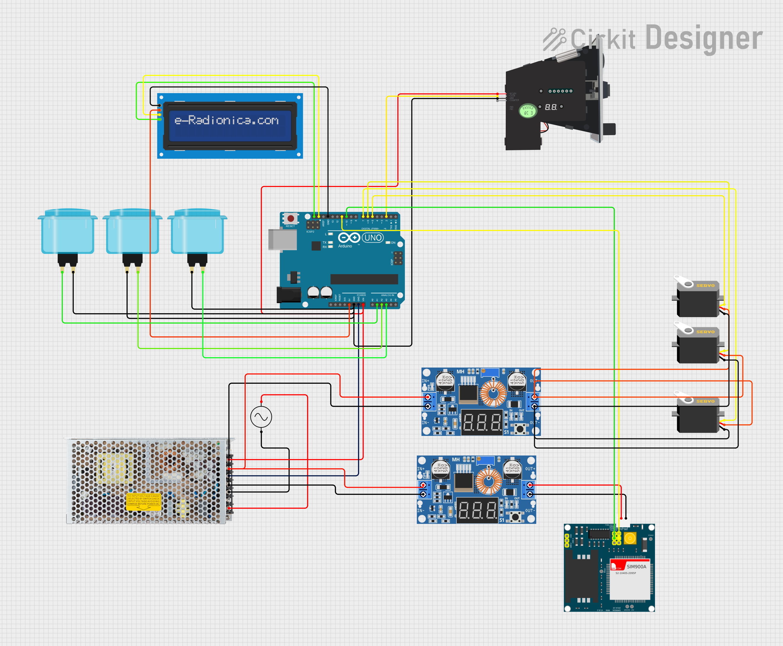
Circuit Documentation
Summary
This document provides a detailed overview of a circuit designed to interface an Arduino UNO with various components including a SIM900A GSM module, an LCD screen, multiple arcade buttons, a multi-coin acceptor, and servos. The circuit is powered by an AC supply connected to a switching power supply, which in turn connects to two XL4015 5A DC Buck Step-down modules to regulate the voltage for different parts of the circuit.
Component List
Arduino UNO
- Microcontroller board based on the ATmega328P
- It has 14 digital input/output pins, 6 analog inputs, a 16 MHz quartz crystal, a USB connection, a power jack, an ICSP header, and a reset button.
Switching Power Supply
- Converts AC input to a stable DC output
- It has connections for AC input, ground, and positive and negative DC outputs.
XL4015 5A DC Buck Step-down
- A DC-to-DC step-down (buck) converter module
- Capable of driving a 5A load with high efficiency, low ripple, and excellent line and load regulation.
AC Supply
- Provides alternating current (AC) power to the circuit
- It has positive and negative AC output terminals.
Multi Coin Acceptor
- Accepts multiple types of coins for vending machines or similar applications
- It has terminals for coin signal output, DC power input, ground, and a counter signal.
SIM900A
- GSM/GPRS module for communication over cellular networks
- It has pins for ground, serial communication (RXD, TXD), power supply, and control signals.
LCD screen 16x2 I2C
- An alphanumeric liquid crystal display with 16 characters per line and 2 lines
- Uses I2C communication protocol, with pins for SCL, SDA, power (VCC), and ground (GND).
Arcade Button (blue)
- A simple push-button switch used in arcade games
- It has a single terminal for the switch contact.
Servo
- A rotary actuator or linear actuator that allows for precise control of angular or linear position, velocity, and acceleration
- It has three pins for ground, power supply, and control signal (pulse).
Wiring Details
Arduino UNO
5Vconnected to LCD screen 16x2 I2CVCCGNDconnected to Arcade Buttons, Multi Coin AcceptorGND, and Switching Power Supply-VVinconnected to Switching Power Supply+Vand Multi Coin AcceptorDC12VA1connected to Arcade Button (blue)A2connected to Arcade Button (blue)A3connected to Arcade Button (blue)SCLconnected to LCD screen 16x2 I2CSCLSDAconnected to LCD screen 16x2 I2CSDAD11connected to SIM900A5VRD10connected to SIM900A5VTD7connected to ServopulseD6connected to ServopulseD5connected to ServopulseD2connected to Multi Coin AcceptorCOIN
Switching Power Supply
ACconnected to AC Supply+veGNDconnected to AC Supply-ve+Vconnected to XL4015 5A DC Buck Step-downInput +and Arduino UNOVin-Vconnected to XL4015 5A DC Buck Step-downInput -and Arduino UNOGND
XL4015 5A DC Buck Step-down
Output +connected to SIM900A5Vand ServosvccOutput -connected to SIM900AGNDand ServosgndInput +connected to Switching Power Supply+VInput -connected to Switching Power Supply-V
Multi Coin Acceptor
COINconnected to Arduino UNOD2DC12Vconnected to Arduino UNOVinGNDconnected to Arcade Buttons and Arduino UNOGND
SIM900A
5Vconnected to XL4015 5A DC Buck Step-downOutput +GNDconnected to XL4015 5A DC Buck Step-downOutput -5VRconnected to Arduino UNOD115VTconnected to Arduino UNOD10
LCD screen 16x2 I2C
SCLconnected to Arduino UNOSCLSDAconnected to Arduino UNOSDAVCCconnected to Arduino UNO5VGNDconnected to Arduino UNOGND
Arcade Button (blue)
- One terminal connected to Arduino UNO
A1,A2, orA3(depending on the specific button)
Servo
pulseconnected to Arduino UNOD7,D6, orD5(depending on the specific servo)vccconnected to XL4015 5A DC Buck Step-downOutput +gndconnected to XL4015 5A DC Buck Step-downOutput -
Documented Code
Arduino UNO Code (sketch.ino)
void setup() {
  // put your setup code here, to run once:

}

void loop() {
  // put your main code here, to run repeatedly:

}
The provided code is a template with empty setup() and loop() functions, which are the standard structure for Arduino sketches. The setup() function is intended to contain initialization code that runs once when the microcontroller is reset or powered on. The loop() function is intended to contain the main logic of the sketch, which runs repeatedly as long as the microcontroller is powered.