Arduino Mega 2560 and ESP32 Based Environmental Monitoring and Control System
Circuit Documentation
Summary
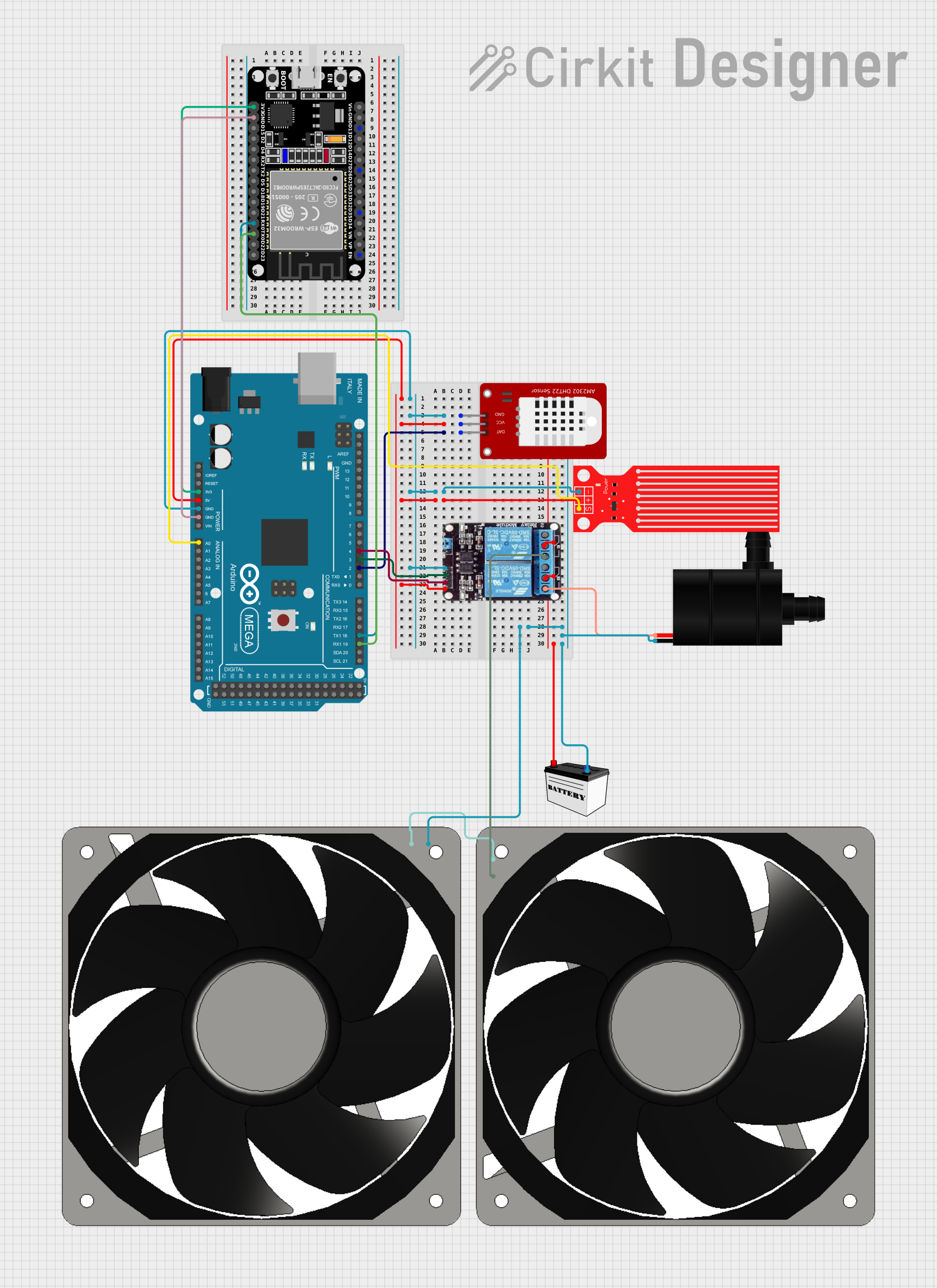
The circuit in question is designed to monitor environmental conditions and control a water pump and fans based on temperature and water level readings. It utilizes an Arduino Mega 2560 as the main microcontroller to interface with a DHT22 temperature and humidity sensor, a water level sensor, and a 2-channel relay module. The relay module controls the power to a water pump and two 120mm 12V fans. An ESP32 microcontroller is also included for potential WiFi capabilities. The system is powered by a 12V battery.
Component List
Arduino Mega 2560
- Microcontroller board based on the ATmega2560
- Provides numerous digital input/output pins, analog inputs, and PWM outputs
- Includes communication interfaces such as UART, SPI, and I2C
DHT22
- Digital temperature and humidity sensor
- Provides calibrated digital output
Water Level Sensor
- Sensor for measuring the level of water
- Outputs an analog signal corresponding to the water level
2-Channel Relay Module
- Module with two relays capable of controlling high power devices
- Each relay has Normally Open (NO) and Normally Closed (NC) connections
12V Battery (Small Size)
- Provides power to the circuit
- 12V output suitable for the fans and water pump
Water Pump
- Electric pump for moving water
- Operates at 12V
120mm Fan 12V
- Two 120mm fans for air circulation
- Operates at 12V
ESP32 (30 Pin)
- Microcontroller with WiFi capability
- Provides a variety of digital and analog I/O pins
Wiring Details
Arduino Mega 2560
5Vpin connected to theVCCpins of the DHT22, Water Level Sensor, and 2ch relayGNDpin connected to theGNDpins of the DHT22, Water Level Sensor, and 2ch relayD2 PWMpin connected to theDATpin of the DHT22A0pin connected to theSIGpin of the Water Level SensorD3 PWMpin connected to theIN1pin of the 2ch relay (controls the water pump)D4 PWMpin connected to theIN2pin of the 2ch relay (controls the fans)3V3pin connected to the3V3pin of the ESP32GNDpin connected to theGNDpin of the ESP32D19/RX1pin connected to theTX0pin of the ESP32 (for serial communication)D18/TX1pin connected to theRX0pin of the ESP32 (for serial communication)
DHT22
VCCpin connected to the5Vof the Arduino Mega 2560GNDpin connected to theGNDof the Arduino Mega 2560DATpin connected to theD2 PWMof the Arduino Mega 2560
Water Level Sensor
VCCpin connected to the5Vof the Arduino Mega 2560GNDpin connected to theGNDof the Arduino Mega 2560SIGpin connected to theA0of the Arduino Mega 2560
2-Channel Relay Module
VCCpin connected to the5Vof the Arduino Mega 2560GNDpin connected to theGNDof the Arduino Mega 2560IN1pin connected to theD3 PWMof the Arduino Mega 2560IN2pin connected to theD4 PWMof the Arduino Mega 2560COMpins connected to theVCCof the 12V BatteryNOpins connected to theVCCof the Water Pump and one of the 120mm fans
12V Battery (Small Size)
VCCpin connected to theCOMpins of the 2ch relayGNDpin connected to theGNDpins of the Water Pump and the 120mm fans
Water Pump
VCCpin connected to theNOpin of the 2ch relayGNDpin connected to theGNDof the 12V Battery
120mm Fans 12V
- One fan's
12V+pin connected to theNOpin of the 2ch relay, and the other fan's12V+pin connected to the12V+of the first fan - Both fans'
GNDpins connected to theGNDof the 12V Battery
ESP32 (30 Pin)
3V3pin connected to the3V3of the Arduino Mega 2560GNDpin connected to theGNDof the Arduino Mega 2560TX0pin connected to theD19/RX1of the Arduino Mega 2560RX0pin connected to theD18/TX1of the Arduino Mega 2560
Documented Code
Arduino Mega 2560 Code (SYSTEM.ino)
#include <DHT.h>
#include <Wire.h>

#define DHTPIN 2
#define DHTTYPE DHT22
#define WATER_LEVEL_PIN A0
#define RELAY_PUMP_PIN 3
#define RELAY_FAN_PIN 4

DHT dht(DHTPIN, DHTTYPE);

void setup() {
  Serial.begin(9600);
  Serial1.begin(115200); // Communication with ESP32
  dht.begin();

  pinMode(WATER_LEVEL_PIN, INPUT);
  pinMode(RELAY_PUMP_PIN, OUTPUT);
  pinMode(RELAY_FAN_PIN, OUTPUT);

  digitalWrite(RELAY_PUMP_PIN, LOW);
  digitalWrite(RELAY_FAN_PIN, LOW);
}

void loop() {
  float temperature = dht.readTemperature();
  float humidity = dht.readHumidity();
  int waterLevel = analogRead(WATER_LEVEL_PIN);

  // Send data to ESP32
  Serial1.print("Temperature: ");
  Serial1.print(temperature);
  Serial1.print(" C, Humidity: ");
  Serial1.print(humidity);
  Serial1.print(" %, Water Level: ");
  Serial1.print(waterLevel);
  Serial1.println(" mm");

  // Check if the temperature is below 15 degrees Celsius
  if (temperature < 15.0 && waterLevel > 3) {
    digitalWrite(RELAY_PUMP_PIN, HIGH); // Activate water pump
    digitalWrite(RELAY_FAN_PIN, HIGH);  // Activate fans
  } else {
    digitalWrite(RELAY_PUMP_PIN, LOW);  // Deactivate water pump
    digitalWrite(RELAY_FAN_PIN, LOW);   // Deactivate fans
  }

  delay(2000); // Wait for 2 seconds before the next reading
}
ESP32 Code (sketch.ino)
#include <WiFi.h>
#include <WebServer.h>

const char* ssid = "your_SSID";
const char* password = "your_PASSWORD";

WebServer server(80);

void setup() {
  Serial.begin(115200);
  WiFi.begin(ssid, password);

  while (WiFi.status() != WL_CONNECTED) {
    delay(1000);
    Serial.println("Connecting to WiFi...");
  }

  Serial.println("Connected to WiFi");

  server.on("/", handleRoot);
  server.begin();
}

void loop() {
  server.handleClient();
}

void handleRoot() {
  if (Serial.available()) {
    String data = Serial.readStringUntil('\n');
    server.send(200, "text/plain", data);
  } else {
    server.send(200, "text/plain", "No data available");
  }
}
(Note: The second code snippet provided for the Arduino Mega 2560 appears to be intended for the ESP32, as it includes WiFi library calls and is written in C++ which is typical for ESP32 sketches. The code snippet is similar to the ESP32 code provided, suggesting a possible duplication or mislabeling in the input data.)