Arduino UNO WiFi CAN Bus Interface with Sensor/Actuator Module
Circuit Documentation
Summary
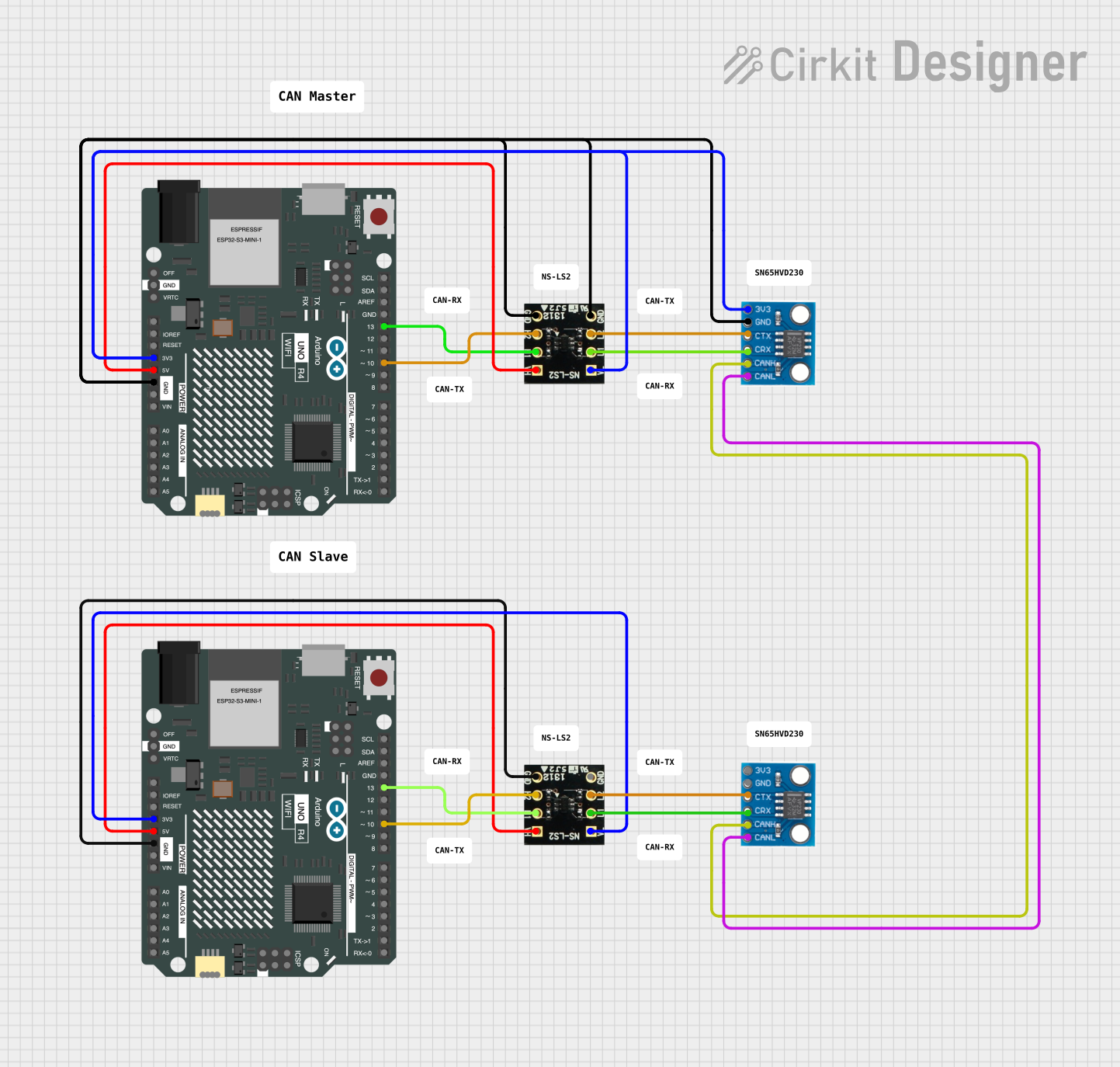
The circuit in question appears to be designed for interfacing an Arduino UNO R4 WiFi with a CAN bus via the CAN_SN65HVD230 transceiver and controlling a dual-channel load switch NS-LS2. The Arduino UNO R4 WiFi is responsible for controlling the load switch and communicating over the CAN bus. The CAN transceivers are connected to each other via their CANH and CANL lines, allowing for CAN bus communication. The load switches are controlled by the Arduino through digital pins and are powered by the Arduino's voltage supply pins.
Component List
Arduino UNO R4 WiFi
- Microcontroller board based on WiFi module
- Provides GPIO pins, I2C interface, power supply pins, and other functionalities
CAN_SN65HVD230
- CAN bus transceiver module
- Interfaces between the CAN protocol controller and the physical wires of the CAN bus
NS-LS2
- Dual-channel load switch
- Controls power to connected loads via high-side switching
Wiring Details
Arduino UNO R4 WiFi
3V3pin provides 3.3V power to the CAN_SN65HVD230 and NS-LS2VLpins5Vpin provides 5V power to the NS-LS2VHpinGNDpin is connected to the ground pins of CAN_SN65HVD230 and NS-LS2D10pin is connected to the NS-LS2H2pin for controlD13pin is connected to the NS-LS2H1pin for control
CAN_SN65HVD230
3V3pin connected to 3.3V power from ArduinoGNDpin connected to groundCTXpin connected to NS-LS2L2pin (purpose unclear without code)CRXpin connected to NS-LS2L1pin (purpose unclear without code)CANHandCANLpins interconnected between two CAN_SN65HVD230 modules for CAN bus communication
NS-LS2
VLpin connected to 3.3V power from ArduinoVHpin connected to 5V power from ArduinoGNDpin connected to groundH1andH2pins controlled by Arduino digital pinsD13andD10respectivelyL1andL2pins connected to CAN_SN65HVD230CRXandCTXpins respectively (purpose unclear without code)
Documented Code
No code has been provided for the microcontrollers in the circuit. Therefore, no code documentation can be generated at this time. The functionality of the circuit, especially the interaction between the CAN transceiver and the load switch, cannot be fully understood without the embedded code that drives the microcontroller.