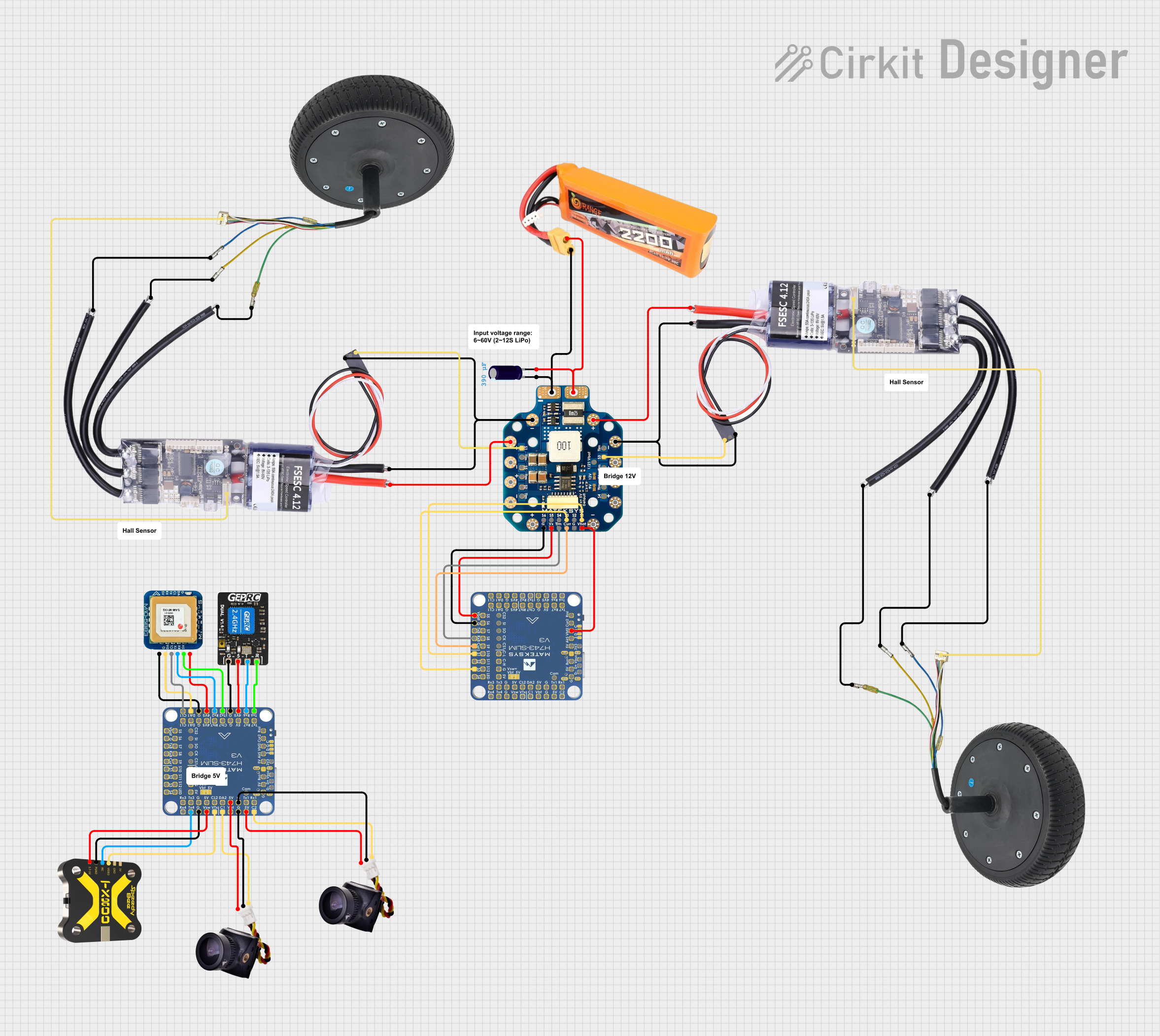
Battery-Powered FPV Drone with Telemetry and Dual Motor Control

Circuit Documentation
Summary
The circuit in question appears to be designed for a mobile platform, possibly a drone or a robotic vehicle, given the presence of components such as a LiPo battery, power distribution board (PDB), motor controllers (Mini FSESC4.12), and motors. It also includes a flight controller (H743-SLIM V3), which suggests that it could be for an unmanned aerial vehicle (UAV). The circuit includes FPV (First Person View) components, indicating that it is likely used for remote control with a video feed. Additionally, there are components for telemetry and GPS, which are typical for navigation and data transmission in remote-controlled vehicles.
Component List
LiPo Battery 2200mAh 30C
- Description: A rechargeable lithium polymer battery used as the power source for the circuit.
- Pins: VCC, GND
PDB-HEX (Power Distribution Board)
- Description: Distributes power from the battery to various components in the circuit.
- Pins: VBAT, GND, VOUT, VDIV, S1-S6, Tlm, VXX, Curr
Electrolytic Capacitor
- Description: Provides filtering for the power supply to reduce voltage spikes and noise.
- Pins: +, -
- Properties: Capacitance: 0.00039 Farads
Motor Wheel
- Description: Actuator for the vehicle's movement.
- Pins: M1, M2, M3, Hall Sensor
H743-SLIM V3 (Flight Controller)
- Description: The central processing unit for the UAV, handling sensor inputs and control outputs.
- Pins: Multiple pins for power, communication, and control signals.
Mini FSESC4.12 (Electronic Speed Controller)
- Description: Controls the speed of the motors based on input signals.
- Pins: VBAT, GND, M1-M3, 5V, SIN, Hall Sensor
FPV Camera
- Description: Captures video for the FPV system.
- Pins: VIN, GND, SIN
FPV VTX (Video Transmitter)
- Description: Transmits the video signal captured by the FPV camera.
- Pins: VIN, GND, IRC, VIDEO
ExpressLRS (Long Range System)
- Description: Provides long-range communication for control and telemetry.
- Pins: GND, 5V, TX, RX
GPS Module
- Description: Provides location data for navigation purposes.
- Pins: 5V, RX, TX, CL, DA, GND
Wiring Details
LiPo Battery 2200mAh 30C
- VCC connected to PDB-HEX VBAT
- GND connected to PDB-HEX GND and Electrolytic Capacitor +
PDB-HEX
- VBAT connected to Electrolytic Capacitor - and H743-SLIM V3 VBAT2
- GND connected to Electrolytic Capacitor +, Mini FSESC4.12 GND (x2), H743-SLIM V3 GND, FPV Camera GND (x2), FPV VTX GND, ExpressLRS GND, GPS GND
- VOUT connected to Mini FSESC4.12 VBAT (x2)
- S1, S3 connected to Mini FSESC4.12 SIN (x2)
- Tlm connected to H743-SLIM V3 RX8: UART8
- Curr connected to H743-SLIM V3 Curr
- VXX connected to H743-SLIM V3 VBAT (filtered)
Electrolytic Capacitor
- connected to PDB-HEX GND
- connected to PDB-HEX VBAT
Motor Wheel (x2)
- M1, M2, M3 connected to corresponding Mini FSESC4.12 M1, M2, M3
- Hall Sensor connected to corresponding Mini FSESC4.12 Hall Sensor
H743-SLIM V3
- GND connected to PDB-HEX GND, FPV Camera GND (x2), FPV VTX GND, ExpressLRS GND, GPS GND
- VBAT (filtered) connected to PDB-HEX VXX
- RX8: UART8 connected to PDB-HEX Tlm
- Curr connected to PDB-HEX Curr
- VBAT2 connected to PDB-HEX VBAT
- S1, S3 connected to PDB-HEX S1, S3
- Tx6: UART6 connected to ExpressLRS RX
- RX6: UART6 connected to ExpressLRS TX
- 4V5 connected to ExpressLRS 5V, GPS 5V
- TX2: UART2 connected to GPS RX
- RX2: UART2 connected to GPS TX
- VSW connected to FPV VTX VIN
- VTX: Video Out connected to FPV VTX VIDEO
- TX4: UART4 connected to FPV VTX IRC
- 5V connected to FPV Camera VIN (x2)
- C1: Camera 1, C2: Camera 2 connected to FPV Camera SIN (x2)
- DA1: I2C1 connected to GPS DA
- CL1: I2C1 connected to GPS CL
Mini FSESC4.12 (x2)
- VBAT connected to PDB-HEX VOUT
- GND connected to PDB-HEX GND
- M1, M2, M3 connected to corresponding Motor Wheel M1, M2, M3
- SIN connected to PDB-HEX S1, S3
- Hall Sensor connected to corresponding Motor Wheel Hall Sensor
FPV Camera (x2)
- VIN connected to H743-SLIM V3 5V
- GND connected to H743-SLIM V3 GND
- SIN connected to H743-SLIM V3 C1: Camera 1, C2: Camera 2
FPV VTX
- VIN connected to H743-SLIM V3 VSW
- GND connected to H743-SLIM V3 GND
- VIDEO connected to H743-SLIM V3 VTX: Video Out
- IRC connected to H743-SLIM V3 TX4: UART4
ExpressLRS
- RX connected to H743-SLIM V3 Tx6: UART6
- TX connected to H743-SLIM V3 RX6: UART6
- 5V connected to H743-SLIM V3 4V5
- GND connected to H743-SLIM V3 GND
GPS Module
- RX connected to H743-SLIM V3 TX2: UART2
- TX connected to H743-SLIM V3 RX2: UART2
- 5V connected to H743-SLIM V3 4V5
- GND connected to H743-SLIM V3 GND
- DA connected to H743-SLIM V3 DA1: I2C1
- CL connected to H743-SLIM V3 CL1: I2C1
Documented Code
No code was provided for the microcontrollers in the circuit. Therefore, this section is not applicable to the current documentation. If code becomes available, it should be documented here with appropriate descriptions and comments for each function and routine.