
Circuit Documentation
Summary
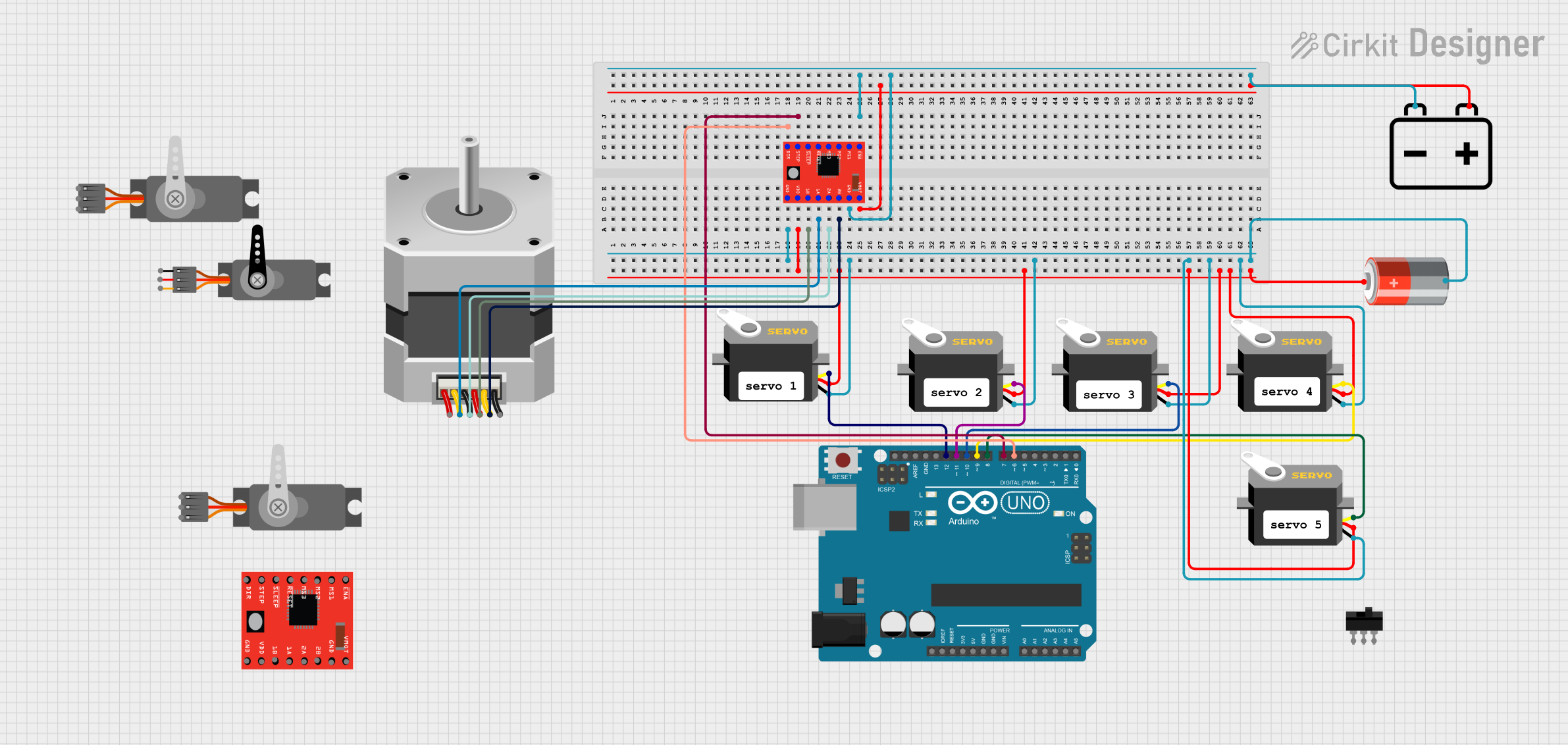
This circuit primarily consists of an Arduino UNO microcontroller, multiple servo motors, a unipolar stepper motor, two A4988 stepper motor drivers, a 12v battery, a 5v battery, and a toggle switch. The Arduino UNO is used to control the servo motors and the stepper motor through the A4988 drivers. The 5v battery powers the servo motors, while the 12v battery is used to power the stepper motor via the A4988 drivers.
Component List
Servo Motors
- Servo: A motor capable of precise position control, typically used in RC vehicles, robotics, and more.
- Servo (Wokwi Compatible): A servo motor compatible with Wokwi simulation, used for precise control in virtual environments.
Microcontroller
- Arduino UNO: A microcontroller board based on the ATmega328P, widely used for building digital devices and interactive objects that can sense and control objects in the physical and digital world.
Motor Drivers
- A4988 Stepper Motor Driver (Red): A complete microstepping motor driver with built-in translator for easy operation.
Motors
- Stepper Motor (Unipolar): A type of DC electric motor that divides a full rotation into a number of equal steps, ideal for precise control of rotation angle and speed.
Power Sources
- 12v Battery: Provides power to the stepper motor through the A4988 driver.
- 5v Battery: Supplies power to the servo motors.
Switches
- Toggle Switch: An electrical switch that is manually actuated by a mechanical lever, handle, or rocking mechanism.
Comments
- Comment: Used to add descriptive notes or annotations within the circuit design for clarity or instructions.
Wiring Details
Servo Motors
- Servo:
gndconnected to the ground network.vccconnected to the 5v power network.pulseconnected to individual digital pins on the Arduino UNO for control signals.
Arduino UNO
- Digital pins
D6,D7,D8,D9,D10,D11, andD12are used to control the direction (DIR), stepping (STEP), and pulse signals for the servo motors.
A4988 Stepper Motor Driver (Red)
GNDconnected to the ground network.DIRconnected to Arduino UNO pinD6.VDDconnected to the 5v power network.STEPconnected to Arduino UNO pinD7.1B,1A,2A,2Bconnected to corresponding pins on the Stepper Motor (Unipolar).ENABLEconnected to the ground network for always enabled operation.VMOTconnected to the 12v battery positive terminal.
Stepper Motor (Unipolar)
- Pins
B,COMMON_1,C,COMMON_2connected to corresponding pins on the A4988 driver.
Power Sources
- 12v Battery:
+connected toVMOTon the A4988 driver.-connected toGNDon the A4988 driver.
- 5v Battery:
+connected to the 5v power network.-connected to the ground network.
Toggle Switch
- Not detailed in the net list, thus assumed to be not connected in this circuit.
Documented Code
void setup() {
  // put your setup code here, to run once:

}

void loop() {
  // put your main code here, to run repeatedly:

}
The provided code is a template for an Arduino sketch with empty setup() and loop() functions. The setup() function is intended for code that needs to run once at the start, such as pin mode declarations. The loop() function is for code that runs continuously, which would include the logic for controlling the servo motors and the stepper motor. However, the actual control code is not provided in the input.