
ESP32-Controlled Weather Monitoring and Water Valve Automation System
View and Edit Project In Cirkit Designer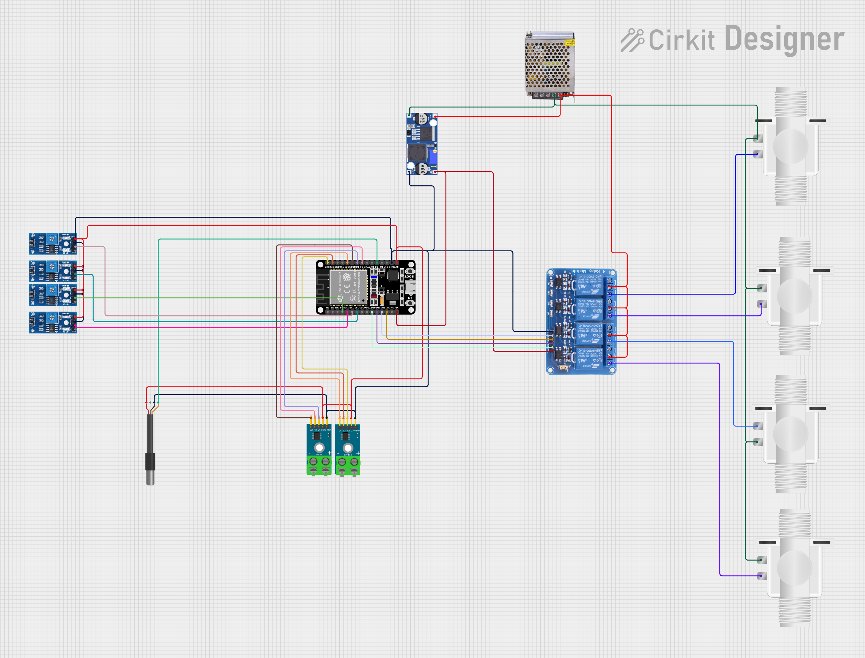
Circuit Documentation
Summary
This circuit is designed to interface an ESP32 microcontroller with a variety of sensors and actuators. It includes relay channels for controlling solenoid valves, temperature sensing via MAX6675 modules and DS18B20 probes, and rain/snow detection using multiple sensor boards. The ESP32 serves as the central processing unit, reading sensor inputs and controlling the relay channels accordingly. The circuit is powered by a 12V 5A power supply, with a buck converter stepping down the voltage to a level suitable for the ESP32 and other 5V components.
Component List
Relay 4 Channel 5v
- A 4-channel relay module capable of controlling higher power circuits with 5V logic signals from the ESP32.
ESP32 (30 pin)
- A 30-pin microcontroller with Wi-Fi and Bluetooth capabilities, used for processing sensor data and controlling the relay channels.
Rain/Snow Sensor - Board
- Multiple sensor boards that detect rain or snow presence through digital and analog signals.
Plastic Solenoid Valve
- Electrically-controlled valves used for controlling the flow of a fluid.
MAX6675 Module
- A thermocouple-to-digital converter that allows the ESP32 to read temperatures from K-type thermocouples.
POWER SUPPLY 12V 5AMP
- A power supply unit that provides 12V and 5A to power the entire circuit.
Buck Converter
- A DC-DC converter that steps down the voltage from 12V to a lower voltage suitable for the ESP32 and other 5V components.
DS18B20 1-Wire Temperature Sensor Probe Cable
- A digital temperature sensor that communicates over a 1-Wire bus.
Wiring Details
Relay 4 Channel 5v
- GND: Connected to the common ground.
- IN1 - IN4: Controlled by ESP32 pins D12, D13, D14, and D27 respectively.
- VCC: Powered by the buck converter's 5V output.
- COM1 - COM4: Connected to the 12V power supply output.
- NO1 - NO4: Connected to the solenoid valves.
ESP32 (30 pin)
- GND: Connected to the common ground.
- Vin: Powered by the buck converter's 5V output.
- D12 - D14, D27: Control signals for the relay module.
- D32 - D35: Digital inputs from the rain/snow sensors.
- D21 - D23, D5, D18, D19: SPI interface for the MAX6675 modules.
- D4: Data line for the DS18B20 temperature sensor.
- 3V3: Powers the rain/snow sensors and the MAX6675 modules.
Rain/Snow Sensor - Board
- GND: Connected to the common ground.
- VCC (5V): Powered by the ESP32's 3V3 pin.
- D0 (Digital): Digital outputs connected to ESP32 pins D32, D33, D34, and D35.
Plastic Solenoid Valve
- pin1: Connected to the common ground of the 12V power supply.
- pin2: Controlled by the relay module's NO1, NO2, NO3, and NO4 contacts.
MAX6675 Module
- GND: Connected to the common ground.
- VCC: Powered by the ESP32's 3V3 pin.
- SCK, CS, SO: SPI interface connected to ESP32 pins D18, D5, D19 for one module and D23, D22, D21 for the other.
POWER SUPPLY 12V 5AMP
- GND (DC): Common ground for the 12V side.
- 12V-24V Output (DC): Powers the relay module and solenoid valves.
Buck Converter
- IN+: Connected to the 12V power supply output.
- IN-: Connected to the 12V power supply ground.
- OUT+: Provides 5V to the ESP32 and relay module.
- OUT-: Connected to the common ground.
DS18B20 1-Wire Temperature Sensor Probe Cable
- GND: Connected to the common ground.
- DQ: Data line connected to ESP32 pin D4.
- VDD: Powered by the ESP32's 3V3 pin.
Documented Code
No code was provided for the microcontrollers in the circuit. The documentation of the code would typically include a description of the functionality, setup and loop functions, and any functions or libraries used to interface with the sensors and actuators.