
Arduino UNO-Based Obstacle-Avoiding Robot with Ultrasonic Sensor and L298N Motor Driver
View and Edit Project In Cirkit Designer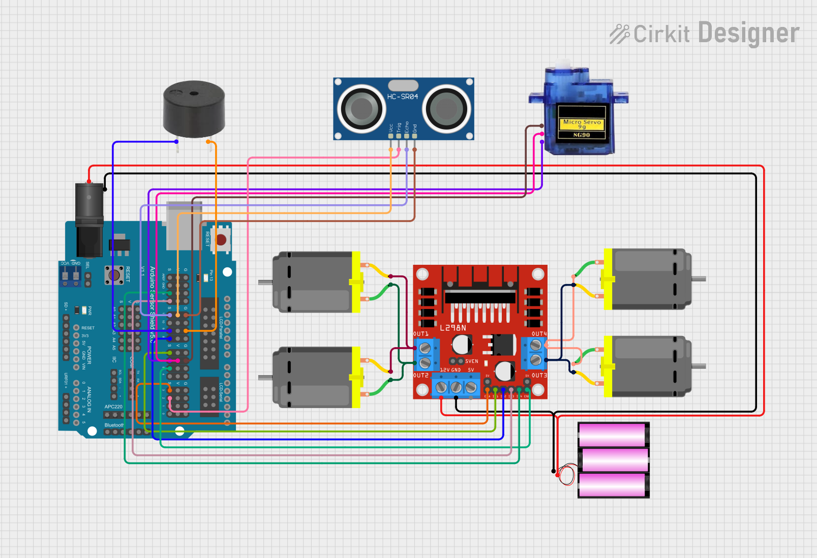
Circuit Documentation
Summary
This document provides a detailed overview of a circuit designed to control multiple DC motors using an L298N motor driver, an Arduino UNO, and various sensors and actuators. The circuit includes a 12V battery for power, a DC barrel jack for power input, and an Arduino Sensor Shield for easy sensor and actuator connections. The system is programmed to control motor movements based on sensor inputs, specifically an ultrasonic sensor for obstacle detection and a servo motor for scanning.
Component List
L298N DC Motor Driver
- Description: Dual H-Bridge motor driver for controlling DC motors.
- Pins: OUT1, OUT2, 12V, GND, 5V, OUT3, OUT4, 5V-ENA-JMP-I, 5V-ENA-JMP-O, +5V-J1, +5V-J2, ENA, IN1, IN2, IN3, IN4, ENB
Arduino UNO
- Description: Microcontroller board based on the ATmega328P.
- Pins: UNUSED, IOREF, Reset, 3.3V, 5V, GND, Vin, A0, A1, A2, A3, A4, A5, SCL, SDA, AREF, D13, D12, D11, D10, D9, D8, D7, D6, D5, D4, D3, D2, D1, D0
Arduino Sensor Shield v5.0
- Description: Expansion shield for Arduino UNO to simplify sensor and actuator connections.
- Pins: VCC, SD-VCC, SD-GND, SD-D11, SD-D10, SD-D13, SD-D12, URF01-VCC, URF01-A0, URF01-A1, URF01-GND, GND, SEL1, SEL2, A0-SIG, A0-VCC, A0-GND, A1-SIG, A1-VCC, A1-GND, A2-SIG, A2-VCC, A2-GND, A3-SIG, A3-VCC, A3-GND, A4-SIG, A4-VCC, A4-GND, A5-SIG, A5-VCC, A5-GND, IIC-SCL, IIC-SDA, IIC-GND, IIC-VCC, COM-TX, COM-RX, COM-GND, COM-VCC, APC220-, APC220-D0, APC220-D1, APC220-VCC, APC220-GND, BLUETOOTH-3V3, BLUETOOTH-GND, BLUETOOTH-D0, BLUETOOTH-D1, BLUETOOTH-VCC, AREF-S, AREF-V, AREF-G, GND-S, GND-V, GND-G, 13-S, 13-V, 13-G, 12-S, 12-V, 12-G, 11-S, 11-V, 11-G, 10-S, 10-V, 10-G, 9-S, 9-V, 9-G, 8-S, 8-V, 8-G, 7-S, 7-V, 7-G, 6-S, 6-V, 6-G, 5-S, 5-V, 5-G, 4-S, 4-V, 4-G, 3-S, 3-V, 3-G, 2-S, 2-V, 2-G, 1-S, 1-V, 1-G, 0-S, 0-V, 0-G, ParallelLCD-VCC, ParallelLCD-D13, ParallelLCD-GND, ParallelLCD-D12, ParallelLCD-D2, ParallelLCD-D11, ParallelLCD-D3, ParallelLCD-D10, ParallelLCD-D4, ParallelLCD-D9, ParallelLCD-D5, ParallelLCD-D8, ParallelLCD-D6, ParallelLCD-D7, SerialLCD-D4, SerialLCD-VCC, SerialLCD-D3, SerialLCD-, SerialLCD-D2, SerialLCD-GND
Battery 12V
- Description: Power source for the circuit.
- Pins: +, -
2.1mm DC Barrel Jack
- Description: Connector for power input.
- Pins: switch, sleeve, center
DC Motor
- Description: Standard DC motor.
- Pins: pin 1, pin 2
Buzzer
- Description: Simple piezoelectric buzzer.
- Pins: PIN, GND
HC-SR04 Ultrasonic Sensor
- Description: Ultrasonic distance sensor.
- Pins: VCC, TRIG, ECHO, GND
Micro Servo 9G
- Description: Small servo motor for precise control.
- Pins: GND, +5V, PWM
Wiring Details
L298N DC Motor Driver
- OUT1: Connected to pin 2 of both DC Motors.
- OUT2: Connected to pin 1 of both DC Motors.
- 12V: Connected to the center pin of the DC Barrel Jack and the positive terminal of the 12V battery.
- GND: Connected to the sleeve pin of the DC Barrel Jack and the negative terminal of the 12V battery.
- OUT3: Connected to pin 2 of the other two DC Motors.
- OUT4: Connected to pin 1 of the other two DC Motors.
- ENA: Connected to pin 3-S of the Arduino Sensor Shield.
- IN1: Connected to pin 7-S of the Arduino Sensor Shield.
- IN2: Connected to pin 8-S of the Arduino Sensor Shield.
- IN3: Connected to pin 12-S of the Arduino Sensor Shield.
- IN4: Connected to pin 13-S of the Arduino Sensor Shield.
- ENB: Connected to pin 5-S of the Arduino Sensor Shield.
Arduino UNO
- Connected to Arduino Sensor Shield v5.0: All pins are mapped directly to the corresponding pins on the Sensor Shield.
Arduino Sensor Shield v5.0
- 3-S: Connected to ENA pin of the L298N DC Motor Driver.
- 7-S: Connected to IN1 pin of the L298N DC Motor Driver.
- 8-S: Connected to IN2 pin of the L298N DC Motor Driver.
- 12-S: Connected to IN3 pin of the L298N DC Motor Driver.
- 13-S: Connected to IN4 pin of the L298N DC Motor Driver.
- 5-S: Connected to ENB pin of the L298N DC Motor Driver.
- 11-S: Connected to ECHO pin of the HC-SR04 Ultrasonic Sensor.
- 11-V: Connected to VCC pin of the HC-SR04 Ultrasonic Sensor.
- 11-G: Connected to GND pin of the HC-SR04 Ultrasonic Sensor.
- 9-S: Connected to PIN of the Buzzer.
- 9-G: Connected to GND of the Buzzer.
- 6-S: Connected to PWM pin of the Micro Servo 9G.
- 6-V: Connected to +5V pin of the Micro Servo 9G.
- 6-G: Connected to GND pin of the Micro Servo 9G.
- 2-S: Connected to TRIG pin of the HC-SR04 Ultrasonic Sensor.
Battery 12V
- +: Connected to the center pin of the DC Barrel Jack and the 12V pin of the L298N DC Motor Driver.
- -: Connected to the sleeve pin of the DC Barrel Jack and the GND pin of the L298N DC Motor Driver.
2.1mm DC Barrel Jack
- center: Connected to the 12V pin of the L298N DC Motor Driver and the positive terminal of the 12V battery.
- sleeve: Connected to the GND pin of the L298N DC Motor Driver and the negative terminal of the 12V battery.
DC Motors
- Motor 1 and Motor 2
- pin 1: Connected to OUT2 of the L298N DC Motor Driver.
- pin 2: Connected to OUT1 of the L298N DC Motor Driver.
- Motor 3 and Motor 4
- pin 1: Connected to OUT4 of the L298N DC Motor Driver.
- pin 2: Connected to OUT3 of the L298N DC Motor Driver.
Buzzer
- PIN: Connected to pin 9-S of the Arduino Sensor Shield.
- GND: Connected to pin 9-G of the Arduino Sensor Shield.
HC-SR04 Ultrasonic Sensor
- VCC: Connected to pin 11-V of the Arduino Sensor Shield.
- TRIG: Connected to pin 2-S of the Arduino Sensor Shield.
- ECHO: Connected to pin 11-S of the Arduino Sensor Shield.
- **