
Wi-Fi Controlled Temperature and Humidity Monitoring System with NodeMCU and DHT11
View and Edit Project In Cirkit Designer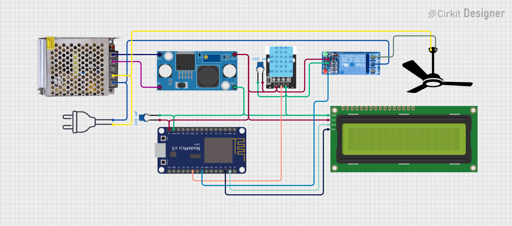
Circuit Documentation
Summary
This circuit is designed to monitor the temperature and humidity of a room using a DHT11 sensor and display the readings on a 16x2 I2C LCD. The system is controlled by a NodeMCU V3 ESP8266 microcontroller, which also connects to the Blynk platform for remote monitoring. A fan is controlled via a 1 Channel Relay to maintain the temperature within a specified threshold. The circuit is powered by a 12V 5A power supply, and the voltage is stepped down using an LM2596 Step Down Module.
Component List
NodeMCU V3 ESP8266
- Description: Microcontroller with WiFi capabilities.
- Pins: A0, GND, VU, S3, S2, S1, SC, S0, SK, 3V3, EN, RST, Vin, D0, D1, D2, D3, D4, D5, D6, D7, D8, RX, TX
KY-015 DHT11 Temperature-Humidity Sensor Module
- Description: Sensor module for measuring temperature and humidity.
- Pins: VCC, GND, DOUT
LM2596 Step Down Module
- Description: Voltage regulator module to step down voltage.
- Pins: OUT-, OUT+, IN-, IN+
1 Channel Relay 5V
- Description: Relay module for controlling high voltage devices.
- Pins: VCC, GND, IN, NC, COM, NO
16x2 I2C LCD
- Description: LCD display with I2C interface.
- Pins: GND, VCC, SDA, SCL
Ceramic Capacitor
- Description: Capacitor for filtering and stabilization.
- Pins: pin0, pin1
- Properties: Capacitance: 0.0000001 Farads
Fan
- Description: Fan for cooling purposes.
- Pins: Neutral, Live
POWER SUPPLY 12V 5AMP
- Description: Power supply unit providing 12V DC.
- Pins: 220V Positive Pole (AC), 220V Negative Pole (AC), GND, GND (DC), 12V-24V Output (DC)
Power 220V
- Description: 220V AC power source.
- Pins: hot wire, neutral wire
Wiring Details
NodeMCU V3 ESP8266
- GND connected to:
- 16x2 I2C LCD (GND)
- KY-015 DHT11 Temperature-Humidity Sensor Module (GND)
- LM2596 Step Down Module (OUT-)
- 1 Channel Relay 5V (GND)
- Ceramic Capacitor (pin0)
- Vin connected to:
- 16x2 I2C LCD (VCC)
- KY-015 DHT11 Temperature-Humidity Sensor Module (VCC)
- LM2596 Step Down Module (OUT+)
- 1 Channel Relay 5V (VCC)
- Ceramic Capacitor (pin1)
- D1 connected to:
- 16x2 I2C LCD (SDA)
- D2 connected to:
- 16x2 I2C LCD (SCL)
- D5 connected to:
- 1 Channel Relay 5V (IN)
- D7 connected to:
- KY-015 DHT11 Temperature-Humidity Sensor Module (DOUT)
KY-015 DHT11 Temperature-Humidity Sensor Module
- GND connected to:
- NodeMCU V3 ESP8266 (GND)
- VCC connected to:
- NodeMCU V3 ESP8266 (Vin)
- DOUT connected to:
- NodeMCU V3 ESP8266 (D7)
LM2596 Step Down Module
- OUT- connected to:
- NodeMCU V3 ESP8266 (GND)
- OUT+ connected to:
- NodeMCU V3 ESP8266 (Vin)
- IN- connected to:
- POWER SUPPLY 12V 5AMP (GND (DC))
- IN+ connected to:
- POWER SUPPLY 12V 5AMP (12V-24V Output (DC))
1 Channel Relay 5V
- GND connected to:
- NodeMCU V3 ESP8266 (GND)
- VCC connected to:
- NodeMCU V3 ESP8266 (Vin)
- IN connected to:
- NodeMCU V3 ESP8266 (D5)
- COM connected to:
- POWER SUPPLY 12V 5AMP (220V Positive Pole (AC))
- Power 220V (neutral wire)
- NO connected to:
- Fan (Live)
16x2 I2C LCD
- GND connected to:
- NodeMCU V3 ESP8266 (GND)
- VCC connected to:
- NodeMCU V3 ESP8266 (Vin)
- SDA connected to:
- NodeMCU V3 ESP8266 (D1)
- SCL connected to:
- NodeMCU V3 ESP8266 (D2)
Ceramic Capacitor
- pin0 connected to:
- NodeMCU V3 ESP8266 (GND)
- pin1 connected to:
- NodeMCU V3 ESP8266 (Vin)
Fan
- Live connected to:
- 1 Channel Relay 5V (NO)
- Neutral connected to:
- POWER SUPPLY 12V 5AMP (220V Negative Pole (AC))
- Power 220V (hot wire)
POWER SUPPLY 12V 5AMP
- 220V Positive Pole (AC) connected to:
- 1 Channel Relay 5V (COM)
- Power 220V (neutral wire)
- 220V Negative Pole (AC) connected to:
- Fan (Neutral)
- Power 220V (hot wire)
- GND (DC) connected to:
- LM2596 Step Down Module (IN-)
- 12V-24V Output (DC) connected to:
- LM2596 Step Down Module (IN+)
Power 220V
- hot wire connected to:
- POWER SUPPLY 12V 5AMP (220V Negative Pole (AC))
- Fan (Neutral)
- neutral wire connected to:
- POWER SUPPLY 12V 5AMP (220V Positive Pole (AC))
- 1 Channel Relay 5V (COM)
Code Documentation
#define BLYNK_TEMPLATE_ID "TMPL6ls4CXNs1"
#define BLYNK_TEMPLATE_NAME "Monitoring Suhhu Kamar Mesin"
#define BLYNK_AUTH_TOKEN "IoFHwZSvj9nxvMqe1Gw1oG1cGkNtSijw"
#include <ESP8266WiFi.h>
#include <BlynkSimpleEsp8266.h>
#include <Wire.h>
#include <LiquidCrystal_I2C.h>
#include "DHT.h"
#define DHTPIN D5     // Digital pin connected to the DHT sensor

#define DHTTYPE DHT11   // DHT 11
#define FAN_PIN D2   // FAN RELAY
WidgetLED FAN(V0);

char auth[] = "IoFHwZSvj9nxvMqe1Gw1oG1cGkNtSijw";
char ssid[] = "Bah";
char pass[] = "14092002";

float humDHT = 0;
float tempDHT = 0;
int Val=0;

// Initialize DHT sensor.
DHT dht(DHTPIN, DHTTYPE);

// Initialize LCD (address 0x27, 16 columns, 2 rows)
LiquidCrystal_I2C lcd(0x27, 16, 2);

void setup() {
  Serial.begin(115200);
  pinMode(FAN_PIN, OUTPUT);
  digitalWrite(FAN_PIN, LOW);
  Serial.println(F("DHTxx test!"));
  dht.begin();
  Blynk.begin(auth, ssid, pass);

  // Initialize the LCD
  lcd.begin();
  lcd.backlight();
  lcd.print("Initializing...");
}

BLYNK_WRITE(V3)
{
  Val = param.asInt(); // assigning incoming value from pin V3 to a variable

  Serial.print(" The Threshold value is: ");
  Serial.println(Val);
  Serial.println();
}

void loop() {
  Blynk.run();

  // Wait a few seconds between measurements.
  delay(2000);

  // Reading temperature or humidity takes about 250 milliseconds!
  // Sensor readings may also be up to 2 seconds 'old' (it's a very slow sensor)
  humDHT = dht.readHumidity();
  // Read temperature as Celsius (the default)
  tempDHT = dht.readTemperature();