
Arduino-Controlled LED Lighting System with Joystick Interface
View and Edit Project In Cirkit Designer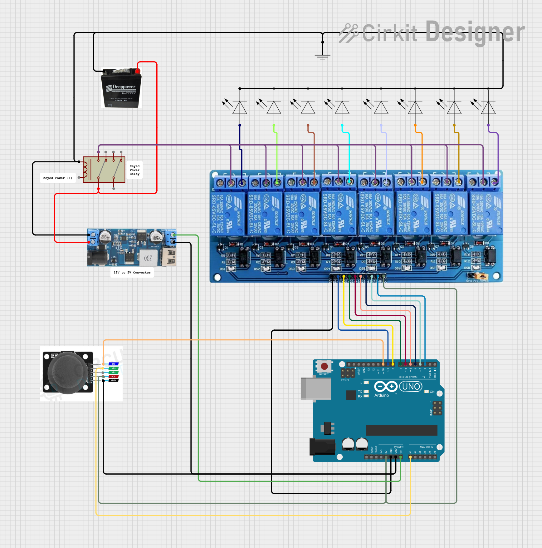
Circuit Documentation
Summary
This circuit is designed to interface an Arduino UNO with a joystick module, multiple LED lights, and an 8-channel relay module. It is powered by a battery through a 12v to 5v step-down power converter. The Arduino UNO controls the relay module based on input from the joystick, which in turn switches the LED lights on and off. A separate relay is also included in the circuit.
Component List
- Arduino UNO: A microcontroller board based on the ATmega328P. It has 14 digital input/output pins, 6 analog inputs, a USB connection, a power jack, an ICSP header, and a reset button.
- Joystick Module: An input device that provides two analog axis inputs and one digital input by a pushbutton.
- LED Light: A light-emitting diode that emits light when a voltage is applied to its terminals.
- 5V 8-Channel Relay Module: A module with 8 relays that can be individually controlled by digital outputs from a microcontroller.
- GND (Ground): A common reference point for the electrical current in the circuit.
- Battery: Provides the power source for the circuit.
- Relay: An electrically operated switch that allows the control of a high-power circuit with a low-power signal.
- 12v to 5v Step Down Power Converter: Converts a 12V input to a stable 5V output, which can be used to power electronic devices.
Wiring Details
Arduino UNO
- 5V: Powers the joystick module and the 8-channel relay module.
- GND: Connected to the ground of the joystick module, the 8-channel relay module, and the step-down power converter.
- Vin: Receives power from the step-down power converter's 5V output.
- A0: Receives analog input from the joystick's VRY pin.
- D10: Connected to the joystick's SW pin to detect button presses.
- D9 - D2: Control the IN1 to IN8 pins of the 8-channel relay module, respectively.
Joystick Module
- VCC: Powered by the Arduino's 5V output.
- GND: Connected to the Arduino's ground.
- VRY: Analog Y-axis output connected to Arduino's A0 pin.
- SW: Pushbutton output connected to Arduino's D10 pin.
LED Lights
- + (Positive): Each LED light's positive terminal is connected to the normally open (NO) terminal of the corresponding relay on the 8-channel relay module.
- - (Negative): Each LED light's negative terminal is connected to the common ground.
5V 8-Channel Relay Module
- VCC: Powered by the Arduino's 5V output.
- GND: Connected to the Arduino's ground.
- IN1 - IN8: Controlled by the Arduino's digital pins D9 to D2, respectively.
- NO: Normally open contacts connected to the positive terminals of the LED lights.
- C: Common contacts, not detailed in the net list but typically connected to a power source.
Ground (GND)
- GND: Serves as the common ground for the entire circuit.
Battery
- + (Positive): Connected to the VIN+ of the step-down power converter and the common 1 terminal of the separate relay.
- - (Negative): Connected to the common ground.
Relay
- Common 1: Connected to the positive terminal of the battery.
- Coil: Connected to the common ground.
- NO 1: Connected to the common (C) terminal of the 8-channel relay module.
12v to 5v Step Down Power Converter
- VIN 9v-36v: Not detailed in the net list.
- VIN+: Connected to the positive terminal of the battery.
- VIN-: Connected to the common ground.
- USB OUTPUT 5V: Not detailed in the net list.
- 5v OUTPUT: Provides power to the Arduino's Vin pin.
- GND: Connected to the common ground.
Documented Code
Arduino UNO Code (sketch.ino)
void setup() {
  // put your setup code here, to run once:

}

void loop() {
  // put your main code here, to run repeatedly:

}
Note: The provided code is a template and does not contain any functional code to control the circuit. It needs to be populated with the logic to read the joystick inputs and control the relay module accordingly.