
WeMos D1 R2 Controlled Relay Switching Circuit for AC Bulb and USB Charger
View and Edit Project In Cirkit Designer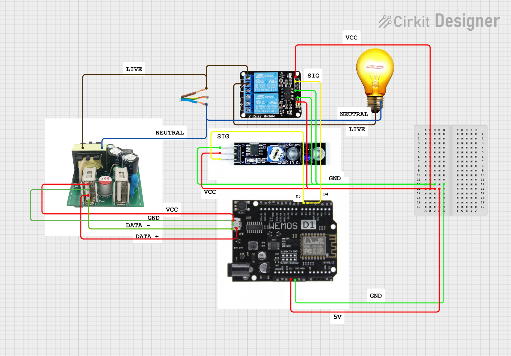
Circuit Documentation
Summary
The circuit described in the provided information consists of several components including a WeMos D1 R2 microcontroller, a 5V 2-Relay module, an AC wire, an AC bulb, a line tracking sensor, and a cellphone charger. The circuit appears to be designed to control an AC bulb and possibly charge a device using the cellphone charger. The WeMos D1 R2 is used as the main controller, interfacing with the relay module to control the power to the AC bulb and receiving signals from the line tracking sensor.
Component List
5v 2-Relay JD-VCC
- Description: A relay module with two relays capable of controlling high power devices.
- Pins: JD-VCC, VCC, GND, IN1, IN2, NO, COM, NC
AC Wire
- Description: A wire used to connect AC power with Line, Earth, and Neutral wires.
- Pins: Line, Earth, Neutral
AC Bulb
- Description: A standard AC bulb.
- Pins: P (Phase), N (Neutral)
Line Tracking Sensor
- Description: A sensor used to detect and follow a line on the ground.
- Pins: GND, VCC, SIG
Cellphone Charger
- Description: A charger used to charge cellphones, with connections for AC input and USB data lines.
- Pins: VCC, GND, D+, D-, L (Line), N (Neutral)
WeMosD1R2
- Description: A microcontroller board based on the ESP8266, compatible with Arduino.
- Pins: SCL/D1, SDA/D2, GND, SCK/D5, MISO/D6, MOSI/D7, SS/D8, D7, D6, D5, D4, D3, SCL, SDA, A0, VIN, 5V, 3V3, IOREF, RX, TX, *DO, VCC, D+, D-
Wiring Details
5v 2-Relay JD-VCC
- GND connected to WeMosD1R2 GND
- VCC connected to WeMosD1R2 5V
- IN2 controlled by WeMosD1R2 D4
- NO connected to AC Wire Line
- COM connected to AC Bulb P
AC Wire
- Line connected to 5v 2-Relay JD-VCC NO and Cellphone Charger L
- Neutral connected to AC Bulb N and Cellphone Charger N
AC Bulb
- P connected to 5v 2-Relay JD-VCC COM
- N connected to AC Wire Neutral
Line Tracking Sensor
- GND connected to WeMosD1R2 GND
- VCC connected to WeMosD1R2 5V
- SIG connected to WeMosD1R2 D5
Cellphone Charger
- VCC connected to WeMosD1R2 VCC
- GND connected to WeMosD1R2 GND
- D+ connected to WeMosD1R2 D+
- D- connected to WeMosD1R2 D-
- L connected to AC Wire Line
- N connected to AC Wire Neutral
WeMosD1R2
- GND connected to 5v 2-Relay JD-VCC GND, Line Tracking Sensor GND, and Cellphone Charger GND
- 5V connected to 5v 2-Relay JD-VCC VCC and Line Tracking Sensor VCC
- D4 controlling 5v 2-Relay JD-VCC IN2
- D5 reading Line Tracking Sensor SIG
- VCC connected to Cellphone Charger VCC
- D+ connected to Cellphone Charger D+
- D- connected to Cellphone Charger D-
Documented Code
No code was provided for the microcontroller. The expected behavior of the microcontroller would be to control the relay based on the input from the line tracking sensor and possibly manage the charging process through the cellphone charger. Without the code, the specific logic and functionality cannot be documented.