
Circuit Documentation
Summary
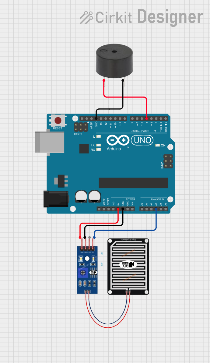
This circuit is designed to detect rain using a rain sensor and trigger a buzzer alarm when rain is detected. The circuit is controlled by an Arduino UNO microcontroller, which reads the analog signal from the rain sensor and activates the buzzer accordingly.
Component List
RAIN SENSOR
- Description: A sensor used to detect the presence of rain.
- Pins: AO, DO, GRD, VCC
- Purpose: To detect rain and provide an analog output signal to the Arduino.
Buzzer
- Description: An audio signaling device.
- Pins: PIN, GND
- Purpose: To produce an audible alarm when rain is detected.
Arduino UNO
- Description: A microcontroller board based on the ATmega328P.
- Pins: UNUSED, IOREF, Reset, 3.3V, 5V, GND, Vin, A0, A1, A2, A3, A4, A5, SCL, SDA, AREF, D13, D12, D11, D10, D9, D8, D7, D6, D5, D4, D3, D2, D1, D0
- Purpose: To read the rain sensor's output and control the buzzer.
Wiring Details
RAIN SENSOR
- AO: Connected to Arduino UNO pin A3
- GRD: Connected to Arduino UNO GND
- VCC: Connected to Arduino UNO 5V
Buzzer
- PIN: Connected to Arduino UNO pin D4
- GND: Connected to Arduino UNO GND
Code Documentation
Arduino UNO Code
void setup() {
  // put your setup code here, to run once:

}

void loop() {
  // put your main code here, to run repeatedly:

}
This code is a basic template for the Arduino UNO. The setup() function is where you initialize your components and settings, and the loop() function is where the main logic of your program runs repeatedly. In this circuit, you would typically read the analog value from the rain sensor in the loop() function and activate the buzzer if rain is detected.