
Circuit Documentation
Summary of the Circuit
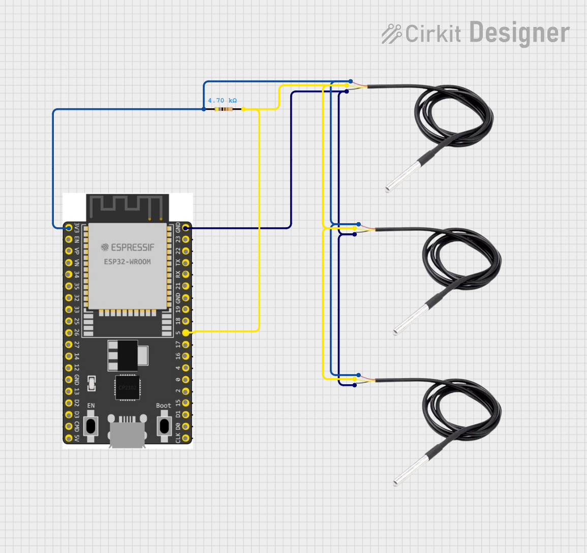
This circuit is designed to interface multiple DS18B20 temperature sensors with an ESP32 Wroom Dev Kit microcontroller. The ESP32 reads temperature data from the sensors and can process or transmit this information as needed. The sensors are powered by the 3.3V supply from the ESP32, and they share a common ground. A pull-up resistor is connected to the data line to ensure proper signal levels for the 1-Wire communication protocol used by the DS18B20 sensors.
Component List
ESP 32 Wroom Dev Kit
- Description: A development board based on the ESP32 microcontroller, which is a powerful, generic Wi-Fi+BT+BLE MCU module that targets a wide variety of applications.
- Pins: 3V3, EN, VP, VN, GPIO 34, GPIO 35, GPIO 32, GPIO 33, GPIO 25, GPIO 26, GPIO 27, GPIO 14, GND, GPIO 13, SD2, SD3, CMD, V5, GPIO 23, GPIO 22, TXD, RXD, GPIO 21, GPIO 19, GPIO 18, GPIO 5, GPIO 17, GPIO 16, GPIO 4, GPIO 0, GPIO 2, GPIO 15, SD1, SD0, CLK
Resistor
- Description: A passive two-terminal electrical component that implements electrical resistance as a circuit element.
- Resistance: 4700 Ohms
DS18B20 Temperature Sensor
- Description: A digital temperature sensor that uses the 1-Wire protocol for communication and provides 9-bit to 12-bit Celsius temperature measurements.
- Pins: signal, GND, vcc
Wiring Details
ESP 32 Wroom Dev Kit
- 3V3: Connected to the VCC pins of all DS18B20 sensors and one end of the Resistor.
- GND: Connected to the GND pins of all DS18B20 sensors.
- GPIO 5: Connected to the signal pins of all DS18B20 sensors and the other end of the Resistor.
Resistor (4.7k Ohm)
- Pin1: Connected to the 3V3 output of the ESP 32 Wroom Dev Kit.
- Pin2: Connected to the signal lines of all DS18B20 sensors.
DS18B20 Temperature Sensor
- VCC: Connected to the 3V3 output of the ESP 32 Wroom Dev Kit.
- GND: Connected to the GND pin of the ESP 32 Wroom Dev Kit.
- Signal: Connected to GPIO 5 of the ESP 32 Wroom Dev Kit through a 4.7k Ohm pull-up resistor.
Documented Code
No code has been provided for the microcontroller. The expected code should initialize the 1-Wire bus on GPIO 5 and read temperature values from the connected DS18B20 sensors. The code should handle the initialization of the sensors, reading and converting the temperature data, and managing any communication protocols if the data is to be transmitted.
Please note that the actual implementation of the code will depend on the specific requirements of the application, such as how frequently the temperature is read, whether the data is displayed or transmitted, and any power-saving modes that may be required.