
ESP32-Based Environmental Monitoring System with Ultrasonic, GPS, GSM, and Rain Sensor
View and Edit Project In Cirkit Designer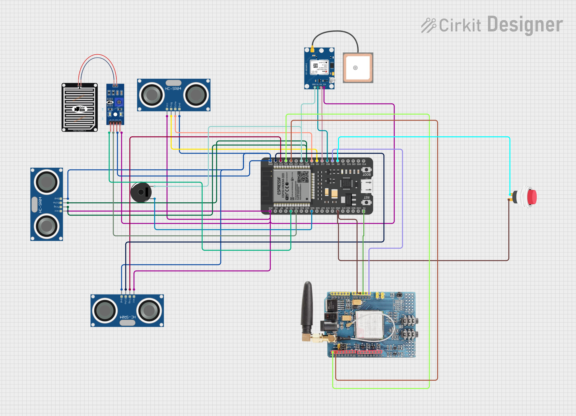
Circuit Documentation
Summary
The circuit in question is a multifunctional system that integrates various sensors and modules to perform tasks such as distance measurement, location tracking, environmental sensing, and communication. The core of the circuit is an ESP32 microcontroller, which is responsible for controlling the sensors and modules, including ultrasonic sensors (HC-SR04), a GPS module (GPS NEO 6M), a rain sensor, a piezo buzzer, a GSM module (GSM SIM900), and a push switch. The ESP32 also handles data processing and communication between the components.
Component List
HC-SR04 Ultrasonic Sensor
- Description: A sensor used for measuring distances using ultrasonic waves.
- Pins: VCC, TRIG, ECHO, GND
GPS NEO 6M
- Description: A GPS module for obtaining geographical location data.
- Pins: VCC, RX, TX, GND
Piezo Buzzer
- Description: An electronic device that emits sound when an electric signal is applied.
- Pins: pin 1, pin 2
2Pin Push Switch
- Description: A simple switch that connects or disconnects an electrical circuit.
- Pins: Input +, Output +
GSM SIM900
- Description: A GSM/GPRS module for cellular communication.
- Pins: A5, A4, A3, A2, A1, A0, 5V, GND, 3.3V, RESET, D0, D1, D2, D3, D4, D5, D6, D7, D8, D9, D10, D11, D12, D13, AREF
RAIN SENSOR
- Description: A sensor used to detect rain or water presence.
- Pins: AO, DO, GRD, VCC
ESP32 - 38 pins
- Description: A powerful microcontroller with Wi-Fi and Bluetooth capabilities.
- Pins: 3V3, EN, SP, SN, G34, G35, G32, G33, G25, G26, G27, G14, G12, GND, G13, SD2, SD3, CMD, 5V, G23, G22, TXD, RXD, G21, G19, G18, G5, G17, G16, G4, G0, G2, G15, SD1, SD0, CLK
Wiring Details
HC-SR04 Ultrasonic Sensor
- VCC connected to 3V3 power supply.
- TRIG connected to ESP32 GPIO pins (G5, G22).
- ECHO connected to ESP32 GPIO pins (G18, G23, G19).
- GND connected to common ground.
GPS NEO 6M
- VCC connected to 3V3 power supply.
- RX connected to ESP32 GPIO pin G17.
- TX connected to ESP32 GPIO pin G16.
- GND connected to common ground.
Piezo Buzzer
- pin 1 connected to ESP32 GPIO pin G25.
- pin 2 connected to common ground.
2Pin Push Switch
- Input + connected to ESP32 GPIO pin G0.
- Output + connected to GSM SIM900 GND and common ground.
GSM SIM900
- 5V connected to ESP32 5V power supply.
- GND connected to common ground.
- RESET connected to ESP32 GPIO pin G4.
- D0 (TX) connected to ESP32 GPIO pin TXD.
- D1 (RX) connected to ESP32 GPIO pin RXD.
RAIN SENSOR
- VCC connected to 3V3 power supply.
- AO connected to ESP32 GPIO pin G34.
- DO connected to ESP32 GPIO pin G35.
- GRD connected to common ground.
Documented Code
There is no code provided for the microcontrollers in the circuit. The code would typically include initialization of the peripherals, configuration of the GPIO pins, and the main application logic to handle sensor data and communication protocols. Without the code, we cannot document the software part of the circuit.