
Arduino UNO Solar-Powered Light-Tracking System with GSM Module
View and Edit Project In Cirkit Designer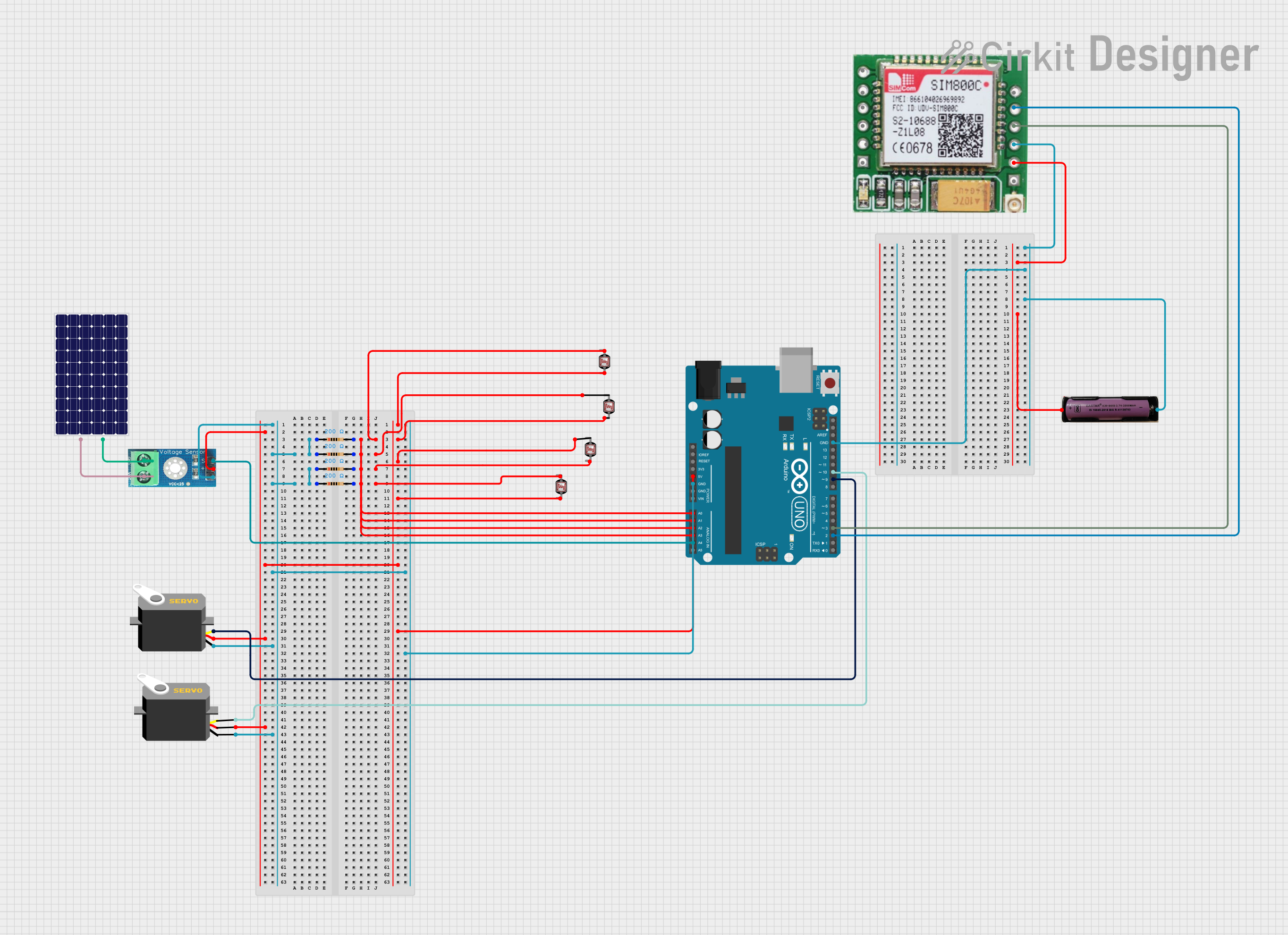
Circuit Documentation
Summary
This document provides a detailed overview of a circuit that includes various components such as resistors, servos, photocells, a GSM module, a voltage sensor, a solar panel, a battery, and an Arduino UNO microcontroller. The circuit is designed to interface these components for a specific application, with the Arduino UNO serving as the central control unit.
Component List
Resistor
- Description: A passive electrical component that implements electrical resistance as a circuit element.
- Pins: pin1, pin2
- Properties:
- Resistance: 200 Ohms
Servo
- Description: An actuator that allows for precise control of angular position.
- Pins: gnd, vcc, pulse
Photocell (LDR)
- Description: A light-dependent resistor that changes its resistance based on the amount of light it is exposed to.
- Pins: pin 0, pin 1
SIM800c GSM Module
- Description: A GSM module used for communication over cellular networks.
- Pins: SPK-, SPK+, MIC-, MIC+, DTR, RING, GND, TXD, RXD, LINK GND, ANT, VCC(3.7 - 4.2)
Arduino UNO
- Description: A microcontroller board based on the ATmega328P.
- Pins: UNUSED, IOREF, Reset, 3.3V, 5V, GND, Vin, A0, A1, A2, A3, A4, A5, SCL, SDA, AREF, D13, D12, D11, D10, D9, D8, D7, D6, D5, D4, D3, D2, D1, D0
Solar Panel
- Description: A device that converts light into electricity.
- Pins: +, -
Voltage Sensor DC 25V
- Description: A sensor used to measure voltage levels up to 25V.
- Pins: +, -, output, gnd, vcc
3.7v Battery
- Description: A battery providing a nominal voltage of 3.7V.
- Pins: +, -
Wiring Details
Resistor
pin1 is connected to:
- pin1 of other resistors
-
- of Voltage Sensor DC 25V
- gnd of Servo
- GND of Arduino UNO
pin2 is connected to:
- pin 0 of Photocell (LDR)
- A3 of Arduino UNO
Servo
gnd is connected to:
- pin1 of Resistors
- GND of Arduino UNO
vcc is connected to:
- 5V of Arduino UNO
-
- of Voltage Sensor DC 25V
pulse is connected to:
- D10 of Arduino UNO
- D9 of Arduino UNO
Photocell (LDR)
pin 0 is connected to:
- pin2 of Resistors
- A3 of Arduino UNO
pin 1 is connected to:
- pin 1 of other Photocells
- 5V of Arduino UNO
SIM800c GSM Module
LINK GND is connected to:
- GND of Arduino UNO
-
- of 3.7v Battery
VCC(3.7 - 4.2) is connected to:
-
- of 3.7v Battery
-
RXD is connected to:
- D3 of Arduino UNO
TXD is connected to:
- D2 of Arduino UNO
Arduino UNO
GND is connected to:
- gnd of Servo
- LINK GND of SIM800c GSM Module
-
- of 3.7v Battery
5V is connected to:
- vcc of Servo
- pin 1 of Photocell (LDR)
-
- of Voltage Sensor DC 25V
A0 is connected to:
- pin2 of Resistor
- pin 0 of Photocell (LDR)
A1 is connected to:
- pin2 of Resistor
- pin 1 of Photocell (LDR)
A2 is connected to:
- pin2 of Resistor
- pin 0 of Photocell (LDR)
A3 is connected to:
- pin2 of Resistor
- pin 0 of Photocell (LDR)
A4 is connected to:
- output of Voltage Sensor DC 25V
D2 is connected to:
- TXD of SIM800c GSM Module
D3 is connected to:
- RXD of SIM800c GSM Module
D9 is connected to:
- pulse of Servo
D10 is connected to:
- pulse of Servo
Solar Panel
+ is connected to:
- vcc of Voltage Sensor DC 25V
- is connected to:
- gnd of Voltage Sensor DC 25V
Voltage Sensor DC 25V
+ is connected to:
-
- of Solar Panel
-
- is connected to:
-
- of Solar Panel
-
output is connected to:
- A4 of Arduino UNO
gnd is connected to:
-
- of Solar Panel
-
vcc is connected to:
- 5V of Arduino UNO
3.7v Battery
+ is connected to:
- VCC(3.7 - 4.2) of SIM800c GSM Module
- is connected to:
- LINK GND of SIM800c GSM Module
- GND of Arduino UNO
Documented Code
Arduino UNO Code (sketch.ino)
void setup() {
  // put your setup code here, to run once:

}

void loop() {
  // put your main code here, to run repeatedly:

}
Additional Documentation (documentation.txt)
This document provides a comprehensive overview of the circuit, including a detailed list of components, their wiring connections, and the code used in the Arduino UNO microcontroller.