
Arduino UNO Controlled Smart Lighting System with Relay and Micro Switches
View and Edit Project In Cirkit Designer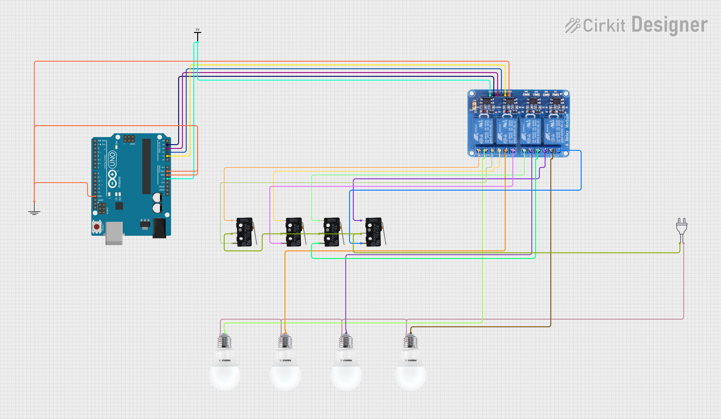
Circuit Documentation
Summary
This circuit involves an Arduino UNO microcontroller controlling a 4-channel relay module, which in turn controls four bulbs. The circuit also includes micro switches for manual control. The power supply for the circuit is provided by a 220V source.
Component List
Arduino UNO
- Description: A microcontroller board based on the ATmega328P.
- Pins: UNUSED, IOREF, Reset, 3.3V, 5V, GND, Vin, A0, A1, A2, A3, A4, A5, SCL, SDA, AREF, D13, D12, D11, D10, D9, D8, D7, D6, D5, D4, D3, D2, D1, D0
Relay 4 Channel 5V
- Description: A relay module that allows the Arduino to control high voltage devices.
- Pins: GND, IN1, IN2, IN3, IN4, VCC, COM1, COM2, COM3, COM4, NO1, NO2, NO3, NO4, NC1, NC2, NC3, NC4
BULB
- Description: A standard light bulb.
- Pins: +, -
Power 220V
- Description: A 220V AC power source.
- Pins: hot wire, neutral wire
Micro Switch
- Description: A small switch used for manual control.
- Pins: COM, NO, NC
Vcc
- Description: Power supply pin.
- Pins: Vcc
GND
- Description: Ground pin.
- Pins: GND
Wiring Details
Arduino UNO
- 5V connected to Vcc of the Vcc component and VCC of the Relay 4 Channel 5V.
- GND connected to GND of the Relay 4 Channel 5V and GND of the GND component.
- A1 connected to IN1 of the Relay 4 Channel 5V.
- A2 connected to IN2 of the Relay 4 Channel 5V.
- A3 connected to IN3 of the Relay 4 Channel 5V.
- A4 connected to IN4 of the Relay 4 Channel 5V.
Relay 4 Channel 5V
- VCC connected to 5V of the Arduino UNO and Vcc of the Vcc component.
- GND connected to GND of the Arduino UNO and GND of the GND component.
- IN1 connected to A1 of the Arduino UNO.
- IN2 connected to A2 of the Arduino UNO.
- IN3 connected to A3 of the Arduino UNO.
- IN4 connected to A4 of the Arduino UNO.
- COM1 connected to + of the first BULB.
- COM2 connected to + of the second BULB.
- COM3 connected to + of the third BULB.
- COM4 connected to + of the fourth BULB.
- NO1 connected to COM of the first Micro Switch.
- NO2 connected to COM of the second Micro Switch.
- NO3 connected to COM of the third Micro Switch.
- NO4 connected to COM of the fourth Micro Switch.
- NC1 connected to NC of the first Micro Switch.
- NC2 connected to NC of the second Micro Switch.
- NC3 connected to NC of the third Micro Switch.
- NC4 connected to NC of the fourth Micro Switch.
BULB
- + of the first BULB connected to COM1 of the Relay 4 Channel 5V.
- + of the second BULB connected to COM2 of the Relay 4 Channel 5V.
- + of the third BULB connected to COM3 of the Relay 4 Channel 5V.
- + of the fourth BULB connected to COM4 of the Relay 4 Channel 5V.
- - of all BULBs connected to neutral wire of the Power 220V.
Power 220V
- hot wire connected to NO of all Micro Switches.
- neutral wire connected to - of all BULBs.
Micro Switch
- COM of the first Micro Switch connected to NO1 of the Relay 4 Channel 5V.
- COM of the second Micro Switch connected to NO2 of the Relay 4 Channel 5V.
- COM of the third Micro Switch connected to NO3 of the Relay 4 Channel 5V.
- COM of the fourth Micro Switch connected to NO4 of the Relay 4 Channel 5V.
- NC of the first Micro Switch connected to NC1 of the Relay 4 Channel 5V.
- NC of the second Micro Switch connected to NC2 of the Relay 4 Channel 5V.
- NC of the third Micro Switch connected to NC3 of the Relay 4 Channel 5V.
- NC of the fourth Micro Switch connected to NC4 of the Relay 4 Channel 5V.
- NO of all Micro Switches connected to hot wire of the Power 220V.
Code Documentation
Arduino UNO Code
void setup() {
  // put your setup code here, to run once:

}

void loop() {
  // put your main code here, to run repeatedly:

}
This code is a basic template for the Arduino UNO. The setup() function is where you initialize your settings, and the loop() function is where you place the code that you want to run continuously. Currently, both functions are empty and need to be filled with the appropriate logic to control the relay module and bulbs.