Cirkit Designer
Your all-in-one circuit design IDE
Home /
Project Documentation
Arduino UNO-Based Environmental Monitoring System with Bluetooth Connectivity
Circuit Documentation
Summary of the Circuit
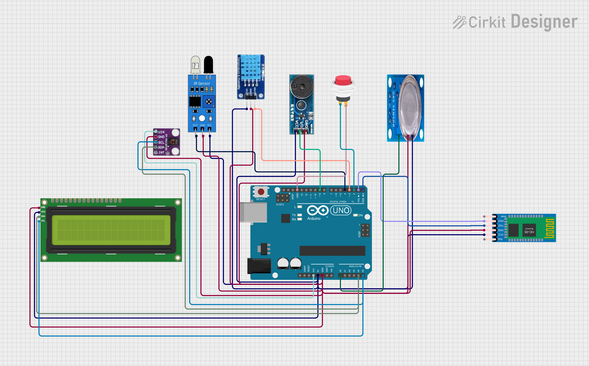
This circuit is designed to interface various sensors and modules with an Arduino UNO microcontroller. The sensors include an MQ-5 gas sensor, an IR sensor, a MAX30100 pulse oximeter, and a DHT11 temperature and humidity sensor. Additionally, the circuit integrates an HC-05 Bluetooth module for wireless communication, an I2C LCD 16x2 screen for display purposes, a buzzer module for audio feedback, and a 2-pin push switch for user input. The Arduino UNO serves as the central processing unit, reading sensor data, controlling the buzzer, and communicating with the Bluetooth module and LCD screen.
Component List
MQ-5 Gas Sensor
- Pins: VCC, GND, Digi Out, Analog out
- Description: A gas sensor for detecting LPG, natural gas, and coal gas.
IR Sensor
- Pins: out, gnd, vcc
- Description: An infrared sensor for detecting proximity or motion.
MAX30100 Pulse Oximeter
- Pins: Vin, gnd, scl, sda, int
- Description: A sensor for measuring blood oxygen saturation and heart rate.
Arduino UNO
- Pins: UNUSED, IOREF, Reset, 3.3V, 5V, GND, Vin, A0-A5, SCL, SDA, AREF, D0-D13
- Description: A microcontroller board based on the ATmega328P.
HC-05 Bluetooth Module
- Pins: Key, VCC, TXD, RXD, State, GND
- Description: A Bluetooth module for wireless communication.
I2C LCD 16x2 Screen
- Pins: SCL, SDA, VCC (5V), GND, VDD, VO, RS, RW, E, D0-D7, BLA, BLK
- Description: A liquid crystal display for showing text and numbers.
DHT11 Temperature and Humidity Sensor
- Pins: DATA, GND, VCC
- Description: A sensor for measuring ambient temperature and humidity.
Buzzer Module
- Pins: GND, Vcc, I/O
- Description: An audio signaling device.
2Pin Push Switch
- Pins: Input +, Output +
- Description: A simple push-button switch for user input.
Wiring Details
MQ-5 Gas Sensor
- VCC connected to Arduino UNO 5V
- GND connected to Arduino UNO GND
- Analog out connected to Arduino UNO A0
IR Sensor
- out connected to Arduino UNO D4
- gnd connected to Arduino UNO GND
- vcc connected to Arduino UNO 5V
MAX30100 Pulse Oximeter
- Vin connected to Arduino UNO 3.3V
- gnd connected to Arduino UNO GND
- scl connected to Arduino UNO A5 (also connected to I2C LCD SCL)
- sda connected to Arduino UNO A4 (also connected to I2C LCD SDA)
HC-05 Bluetooth Module
- VCC connected to Arduino UNO 5V
- GND connected to Arduino UNO GND
- TXD connected to Arduino UNO D0
- RXD connected to Arduino UNO D1
I2C LCD 16x2 Screen
- SCL connected to Arduino UNO A5 (also connected to MAX30100 scl)
- SDA connected to Arduino UNO A4 (also connected to MAX30100 sda)
- VCC (5V) connected to Arduino UNO 5V
- GND connected to Arduino UNO GND
DHT11 Temperature and Humidity Sensor
- DATA connected to Arduino UNO D3
- GND connected to Arduino UNO GND
- VCC connected to Arduino UNO 5V
Buzzer Module
- I/O connected to Arduino UNO D9
- GND connected to Arduino UNO GND
- Vcc connected to Arduino UNO 5V
2Pin Push Switch
- Input + connected to Arduino UNO D2
- Output + connected to Arduino UNO GND
Documented Code
Arduino UNO Code (sketch.ino)
void setup() {
  // put your setup code here, to run once:

}

void loop() {
  // put your main code here, to run repeatedly:

}
Additional Notes
- The provided code is a template and does not contain any functional implementation. The user is expected to fill in the setup and loop functions with the logic required to operate the circuit as intended.
- The code for the Arduino UNO should be written to initialize the sensors and modules, read sensor data, control the buzzer, manage the display on the LCD, and handle Bluetooth communication.
- The documentation file (documentation.txt) is empty and can be used to add further explanations or instructions related to the code.