
IR Sensor-Controlled Dual Motor System with Relay and LED Indicator
View and Edit Project In Cirkit Designer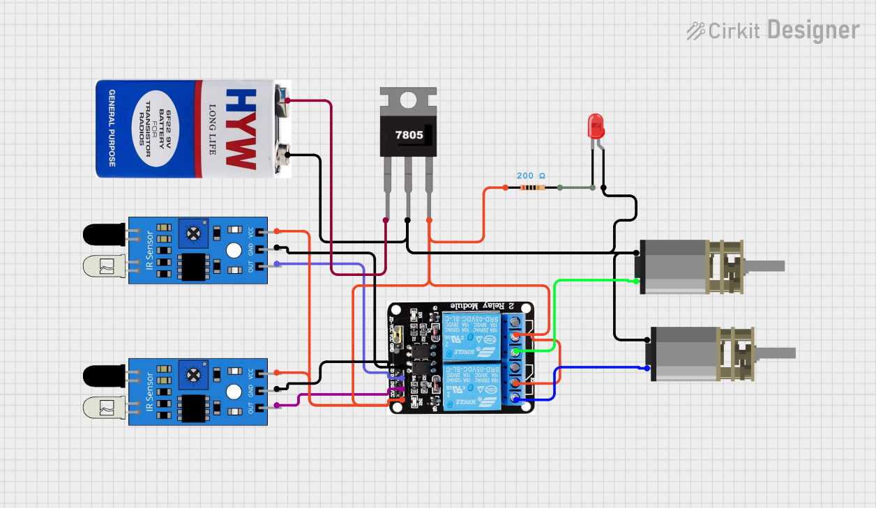
Circuit Documentation
Summary
This circuit involves multiple components including IR sensors, a voltage regulator, a relay module, a 9V battery, DC motors, an LED, and a resistor. The circuit is designed to control the operation of DC motors based on the input from IR sensors, with power regulation provided by a 7805 voltage regulator. The relay module is used to switch the motors on and off, and an LED is included for visual indication.
Component List
IR Sensor
- Pins: out, gnd, vcc
- Description: Infrared sensor used to detect objects.
- Purpose: Provides input signals to the relay module based on object detection.
7805 Voltage Regulator
- Pins: Vin, Gnd, Vout
- Description: Voltage regulator that outputs a stable 5V.
- Purpose: Regulates the 9V battery voltage down to 5V for other components.
5V 2-Relay JD-VCC Module
- Pins: JD-VCC, VCC, GND, IN1, IN2, NO, COM, NC
- Description: Relay module used to control high-power devices.
- Purpose: Switches the DC motors on and off based on input from the IR sensors.
9V Battery
- Pins: +, -
- Description: Power source for the circuit.
- Purpose: Provides the initial power supply.
DC Mini Metal Gear Motor
- Pins: IN1, IN2
- Description: Small DC motor with metal gears.
- Purpose: Actuates mechanical movement in the system.
LED: Two Pin (Red)
- Pins: cathode, anode
- Description: Red LED for visual indication.
- Purpose: Indicates the status of the circuit.
Resistor
- Pins: pin1, pin2
- Description: 200 Ohms resistor.
- Purpose: Limits current to the LED.
Wiring Details
IR Sensor 1
- Pins:
- out: Connected to IN2 of the relay module.
- gnd: Connected to GND of the relay module and IR Sensor 2.
- vcc: Connected to Vout of the 7805 voltage regulator.
IR Sensor 2
- Pins:
- out: Connected to IN1 of the relay module.
- gnd: Connected to GND of the relay module and IR Sensor 1.
- vcc: Connected to Vout of the 7805 voltage regulator.
7805 Voltage Regulator
- Pins:
- Vin: Connected to the + terminal of the 9V battery.
- Gnd: Connected to the anode of the LED, the - terminal of the 9V battery, and IN1 of both DC motors.
- Vout: Connected to pin1 of the resistor, VCC, and COM of the relay module, and vcc of both IR sensors.
5V 2-Relay JD-VCC Module
- Pins:
- JD-VCC: Not connected.
- VCC: Connected to Vout of the 7805 voltage regulator.
- GND: Connected to gnd of both IR sensors.
- IN1: Connected to out of IR Sensor 2.
- IN2: Connected to out of IR Sensor 1.
- NO: Connected to IN2 of both DC motors.
- COM: Connected to Vout of the 7805 voltage regulator.
9V Battery
- Pins:
- +: Connected to Vin of the 7805 voltage regulator.
- -: Connected to Gnd of the 7805 voltage regulator, the anode of the LED, and IN1 of both DC motors.
DC Mini Metal Gear Motor 1
- Pins:
- IN1: Connected to Gnd of the 7805 voltage regulator.
- IN2: Connected to NO of the relay module.
DC Mini Metal Gear Motor 2
- Pins:
- IN1: Connected to Gnd of the 7805 voltage regulator.
- IN2: Connected to NO of the relay module.
LED: Two Pin (Red)
- Pins:
- cathode: Connected to pin2 of the resistor.
- anode: Connected to Gnd of the 7805 voltage regulator and the - terminal of the 9V battery.
Resistor
- Pins:
- pin1: Connected to Vout of the 7805 voltage regulator.
- pin2: Connected to the cathode of the LED.
Code
No microcontroller code is provided for this circuit.