
ESP32 Mini-Based Smart Timekeeper with OLED Display and Battery Charging
View and Edit Project In Cirkit Designer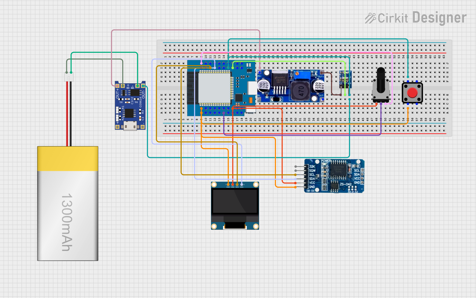
Circuit Documentation
Summary
This circuit integrates various components to perform a set of functions that are not explicitly defined by the provided information. The circuit includes a microcontroller (ESP32 Mini), a display module (0.96" OLED), a charging module (TP4056), a real-time clock (RTC DS3231), voltage regulators (LM2596 and AMS1117 3.3), a LiPoly battery, a rotary potentiometer, and a red pushbutton. The ESP32 Mini is the central processing unit, interfacing with the OLED display, RTC, and other peripherals. The TP4056 module is used for charging the LiPoly battery, which provides power to the circuit. The voltage regulators ensure that the components receive the correct operating voltages. The rotary potentiometer and pushbutton serve as input devices.
Component List
0.96" OLED
- Description: A small OLED display for visual output.
- Pins: GND, VDD, SCK, SDA
ESP32 Mini
- Description: A powerful microcontroller with Wi-Fi and Bluetooth capabilities.
- Pins: GND, GPIOs, VCC, 3.3V, TXD, RXD, SDx, TCK, TDI, TMS, TD0, RST, CLK, NC, SVN, SVP
TP4056
- Description: A lithium battery charging module.
- Pins: OUT-, B-, B+, OUT+, IN-, IN+
LiPoly Battery (1300mAh)
- Description: A rechargeable lithium polymer battery.
- Pins: positive, negative
RTC DS3231
- Description: A real-time clock module for timekeeping.
- Pins: 32K, SQW, SCL, SDA, VCC, GND
LM2596
- Description: A voltage regulator for stepping down voltage.
- Pins: IN, OUT
AMS1117 3.3
- Description: A 3.3V voltage regulator.
- Pins: VIN, OUT, GND
Rotary Potentiometer
- Description: A variable resistor with a knob for adjusting voltage or current.
- Pins: leg1, wiper, leg2
- Properties: Resistance - 10,000 Ohms
Red Pushbutton
- Description: A momentary pushbutton switch for user input.
- Pins: Pin 1, Pin 2, Pin 3, Pin 4
Wiring Details
0.96" OLED
- GND connected to system ground.
- VDD connected to 3.3V power supply.
- SCK connected to ESP32 Mini GPIO22 (SCL).
- SDA connected to ESP32 Mini GPIO21 (SDA).
ESP32 Mini
- GND connected to system ground.
- GPIOs connected to various components as per functionality.
- VCC connected to AMS1117 3.3V OUT.
- 3.3V connected to various components requiring 3.3V.
- TXD, RXD used for serial communication.
- SDx, TCK, TDI, TMS, TD0 for debugging and programming.
- RST connected to Red Pushbutton Pin 2 for reset functionality.
- CLK for clock signals.
- NC (No Connection) pins are not connected.
- SVN, SVP are not specified in the wiring details.
TP4056
- OUT- connected to system ground.
- B- connected to LiPoly Battery negative.
- B+ connected to LiPoly Battery positive.
- OUT+ connected to LM2596 IN.
LiPoly Battery (1300mAh)
- positive connected to TP4056 B+.
- negative connected to TP4056 B-.
RTC DS3231
- GND connected to system ground.
- SCL connected to ESP32 Mini GPIO22.
- SDA connected to ESP32 Mini GPIO21.
- VCC connected to 3.3V power supply.
LM2596
- IN connected to TP4056 OUT+.
- OUT connected to AMS1117 3.3V VIN.
AMS1117 3.3
- VIN connected to LM2596 OUT.
- OUT connected to ESP32 Mini VCC.
- GND connected to system ground.
Rotary Potentiometer
- leg1 connected to 3.3V power supply.
- wiper connected to ESP32 Mini GPIO34.
- leg2 connected to system ground.
Red Pushbutton
- Pin 1 connected to system ground.
- Pin 2 connected to ESP32 Mini RST.
Code Documentation
No code has been provided for the microcontrollers in the circuit. Therefore, this section is not applicable for the current documentation. When code is available, it should be documented here with descriptions of the functionality implemented by each code segment, including setup, loop, and function definitions.