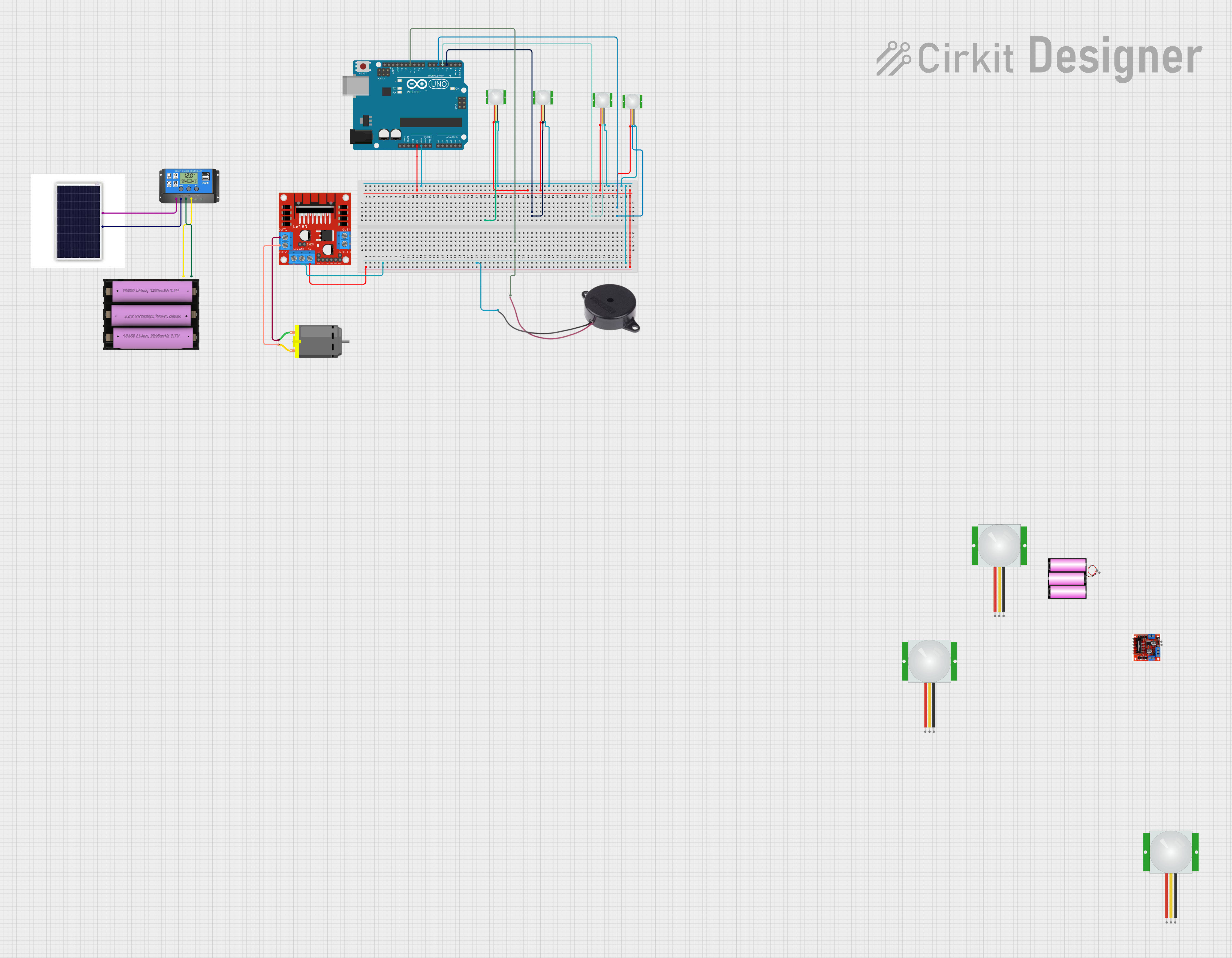
Arduino-Controlled Solar-Powered PIR Motion Detection System with DC Motor and Buzzer Alerts

Circuit Documentation
Summary
This circuit integrates various components including an Arduino UNO, a set of PIR sensors, a DC motor, a buzzer, a motor driver, a solar panel with a charge controller, and a battery. The Arduino UNO serves as the central microcontroller, interfacing with PIR sensors for motion detection, controlling a buzzer for alerts, and managing a DC motor through a motor driver. The power management is handled by a solar panel connected to a solar charge controller, which charges a 7V battery. The battery provides power to the system.
Component List
- Arduino UNO: A microcontroller board based on the ATmega328P, featuring digital and analog I/O pins.
- Battery 12V: A 12V power source.
- Set Battery (7V): A 7V power source.
- Solar Panel: A photovoltaic panel for converting solar energy into electrical power.
- Solar Charge Controller: A device that regulates the voltage and current coming from the solar panels going to the battery.
- L298N Motor Driver Controller Board Module: A module for controlling DC motors with logic signals from a microcontroller.
- PIR Sensor: A motion sensor that detects changes in infrared radiation levels.
- DC Motor: An electric motor that runs on direct current electricity.
- Buzzer: An audio signaling device.
Wiring Details
Arduino UNO
- 5V: Connected to the 5V pin of the L298N DC motor driver and VDD pins of PIR sensors.
- GND: Connected to the GND pin of the L298N DC motor driver, NEGATIVE pin of the buzzer, and GND pins of PIR sensors.
- D11: Connected to the POSITIVE pin of the buzzer.
- D3, D4, D5: Connected to the SIG pins of different PIR sensors.
Battery 12V
- +: Not connected in the provided net list.
- -: Not connected in the provided net list.
Set Battery (7V)
- +: Connected to the Battery + pin of the Solar Charge Controller.
- -: Connected to the Battery - pin of the Solar Charge Controller.
Solar Panel
- Vcc: Connected to the Solar Cell + pin of the Solar Charge Controller.
- Gnd: Connected to the Solar Cell - pin of the Solar Charge Controller.
Solar Charge Controller
- Solar Cell +: Connected to the Vcc pin of the Solar Panel.
- Solar Cell -: Connected to the Gnd pin of the Solar Panel.
- Battery +: Connected to the + pin of the Set Battery (7V).
- Battery -: Connected to the - pin of the Set Battery (7V).
- Load +: Not connected in the provided net list.
- Load -: Not connected in the provided net list.
L298N Motor Driver
- 5V: Connected to the 5V pin of the Arduino UNO.
- GND: Connected to the GND pin of the Arduino UNO.
- OUT1: Connected to pin 1 of the DC Motor.
- OUT2: Connected to pin 2 of the DC Motor.
PIR Sensors
- VDD: Connected to the 5V pin of the Arduino UNO.
- SIG: Connected to digital pins D3, D4, D5 of the Arduino UNO (each sensor to a separate pin).
- GND: Connected to the GND pin of the Arduino UNO.
DC Motor
- Pin 1: Connected to the OUT1 pin of the L298N Motor Driver.
- Pin 2: Connected to the OUT2 pin of the L298N Motor Driver.
Buzzer
- POSITIVE: Connected to the D11 pin of the Arduino UNO.
- NEGATIVE: Connected to the GND pin of the Arduino UNO.
Documented Code
Arduino UNO Code (sketch.ino)
void setup() {
  // put your setup code here, to run once:

}

void loop() {
  // put your main code here, to run repeatedly:

}
Note: The provided code is a template and does not include specific functionality. It needs to be populated with the logic for interacting with the PIR sensors, motor driver, and buzzer based on the requirements of the circuit's application.