
Arduino and ESP8266-Based Renewable Energy Management System with Wi-Fi Connectivity
View and Edit Project In Cirkit Designer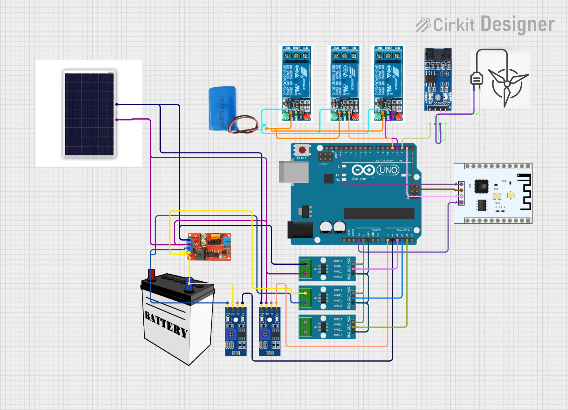
Circuit Documentation
Summary
This circuit is designed to manage and monitor a renewable energy system comprising solar panels, a wind turbine, and a battery. The system uses an Arduino UNO microcontroller to read sensor data, control relays, and communicate with an ESP8266 WiFi module for remote monitoring. The circuit includes current sensors, voltage sensors, and relays to manage the power flow between the solar panels, wind turbine, and battery.
Component List
Arduino UNO
- Description: Microcontroller board based on the ATmega328P.
- Pins: UNUSED, IOREF, Reset, 3.3V, 5V, GND, Vin, A0, A1, A2, A3, A4, A5, SCL, SDA, AREF, D13, D12, D11, D10, D9, D8, D7, D6, D5, D4, D3, D2, D1, D0
12V Battery
- Description: Provides 12V power supply.
- Pins: VCC, GND
Solar Panel
- Description: Converts sunlight into electrical energy.
- Pins: Vcc, Gnd
Solar Panel Regulator 5A MPPT Controller Battery Charging 9V/12V/24V/Auto Switch
- Description: Manages the charging of the battery from the solar panel.
- Pins: +Vin, Ground, battery (-), battery(+)
LM393
- Description: Voltage comparator.
- Pins: A0, D0, GND, VCC
5V Relay
- Description: Electromechanical switch controlled by the Arduino.
- Pins: Normally Open, Common terminal, Normally Closed, In, GND, VCC
5V Battery
- Description: Provides 5V power supply.
- Pins: positive, negative
ESP8266 ESP-201 WiFi Module
- Description: WiFi module for wireless communication.
- Pins: 3.3V, IO4, D3, D1, D0, CMD, CLK, D2, IO2, IO0, GND, IO5, T_OUT, RST, CHIP_EN, XPD, IO14, IO12, IO13, IO15, RX, TX
Wind Turbine
- Description: Converts wind energy into electrical energy.
- Pins: +, -
ACS712 Current Sensor 5A 20A 30A
- Description: Measures current flow.
- Pins: 1, 2, GND, OUT, VCC
Wiring Details
Arduino UNO
- 3.3V connected to 3.3V of ESP8266 ESP-201 WiFi Module
- 5V connected to VCC of ACS712 Current Sensors
- GND connected to GND of ACS712 Current Sensors and ESP8266 ESP-201 WiFi Module
- A0 connected to A0 of LM393
- A1 connected to A0 of LM393
- A2 connected to OUT of ACS712 Current Sensor
- A3 connected to OUT of ACS712 Current Sensor
- A4 connected to OUT of ACS712 Current Sensor
- D2 connected to A0 of LM393
- D3 connected to In of 5V Relay
- D4 connected to In of 5V Relay
- D1 connected to RX of ESP8266 ESP-201 WiFi Module
- D0 connected to TX of ESP8266 ESP-201 WiFi Module
12V Battery
- VCC connected to battery(+) of Solar Panel Regulator and 2 of ACS712 Current Sensor
- GND connected to battery(-) of Solar Panel Regulator and 1 of ACS712 Current Sensor
Solar Panel
- Vcc connected to +Vin of Solar Panel Regulator
- Gnd connected to Ground of Solar Panel Regulator
Solar Panel Regulator
- +Vin connected to Vcc of Solar Panel
- Ground connected to Gnd of Solar Panel
- battery(+) connected to VCC of LM393 and 2 of ACS712 Current Sensor
- battery(-) connected to GND of LM393 and 1 of ACS712 Current Sensor
LM393
- VCC connected to battery(+) of Solar Panel Regulator
- GND connected to battery(-) of Solar Panel Regulator
- A0 connected to A0 of Arduino UNO
- A0 connected to A1 of Arduino UNO
- A0 connected to D2 of Arduino UNO
5V Relay
- In connected to D3 of Arduino UNO
- In connected to D4 of Arduino UNO
- GND connected to negative of 5V Battery
- VCC connected to positive of 5V Battery
5V Battery
- positive connected to VCC of 5V Relay
- negative connected to GND of 5V Relay
ESP8266 ESP-201 WiFi Module
- 3.3V connected to 3.3V of Arduino UNO
- GND connected to GND of Arduino UNO
- RX connected to D1 of Arduino UNO
- TX connected to D0 of Arduino UNO
Wind Turbine
- + connected to VCC of LM393
- - connected to GND of LM393
ACS712 Current Sensor
- VCC connected to 5V of Arduino UNO
- GND connected to GND of Arduino UNO
- OUT connected to A2 of Arduino UNO
- OUT connected to A3 of Arduino UNO
- OUT connected to A4 of Arduino UNO
Documented Code
// Bibliothèques nécessaires
//#include <SoftwareSerial.h>
// #include <ESP8266WiFi.h>
// #include <ThingSpeak.h>

// Déclarations des broches
const int PV_VOLTAGE_PIN = A0;
const int BATTERY_VOLTAGE_PIN = A1;
const int PV_CURRENT_PIN = A2;
const int BATTERY_CURRENT_PIN = A3;
const int DEMAND_PIN = A4;
const int WIND_SENSOR_PIN = 2; // Entrée digitale pour l'anémomètre

const int RELAY_PV_PIN = 3;
const int RELAY_BATTERY_PIN = 4;
const int RELAY_WIND_PIN = 5;

// Variables pour les mesures
float pvVoltage = 0.0;
float batteryVoltage = 0.0;
float pvCurrent = 0.0;
float batteryCurrent = 0.0;
float windSpeed = 0.0;
float demand = 0.0;

// Variables pour la vitesse du vent
unsigned long lastPulseTime = 0;
int pulseCount = 0;

// Paramètres Wi-Fi et ThingSpeak
//const char* ssid = "Votre_SSID";
//const char* password = "Votre_Mot_de_Passe";
//unsigned long myChannelNumber = YOUR_CHANNEL_NUMBER;
//const char* myWriteAPIKey = "VOTRE_API_KEY";

// Fonction d'initialisation
void setup() {
  // Initialisation de la communication série
  Serial.begin(9600);
  // Initialisation des relais
  pinMode(RELAY_PV_PIN, OUTPUT);
  pinMode(RELAY_BATTERY_PIN, OUTPUT);
  pinMode(RELAY_WIND_PIN, OUTPUT);
  // Initialisation des capteurs
  pinMode(PV_VOLTAGE_PIN, INPUT);
  pinMode(BATTERY_VOLTAGE_PIN, INPUT);
  pinMode(PV_CURRENT_PIN, INPUT);
  pinMode(BATTERY_CURRENT_PIN, INPUT);
  pinMode(DEMAND_PIN, INPUT);
  pinMode(WIND_SENSOR_PIN, INPUT_PULLUP);

  // Initialisation des relais à l'état désactivé
  digitalWrite(RELAY_PV_PIN, LOW);
  digitalWrite(RELAY_BATTERY_PIN, LOW);
  digitalWrite(RELAY_WIND_PIN, LOW);

  // Connexion au réseau Wi-Fi
 // WiFi.mode(WIFI_STA);
 // WiFi.begin(ssid, password);

  //Serial.print("Connexion au Wi-Fi");
 // while (WiFi.status() != WL_CONNECTED) {
 //   delay(500);
 //   Serial.print(".");
 // }
 // Serial.println(" Connecté !");

  // Initialisation de ThingSpeak
 // ThingSpeak.begin(WiFi);

  // Attendre la connexion
 // delay(1000);
}

// Fonction de boucle principale
void loop() {
  // Lecture des capteurs
  pvVoltage = analogRead(PV_VOLTAGE_PIN) * (5.0 / 1023.0) * 11