
Arduino Mega 2560 Security System with PIR Motion Sensor and Keypad
View and Edit Project In Cirkit Designer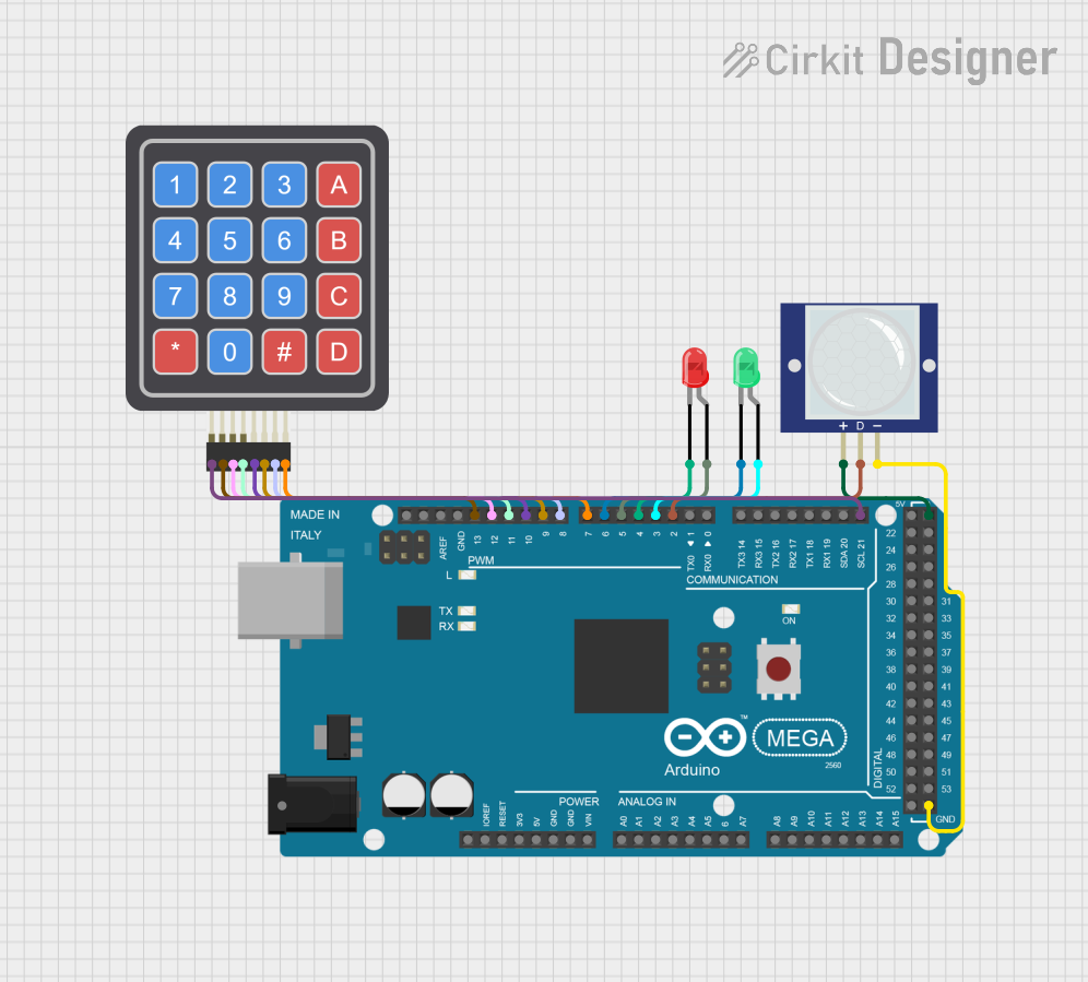
Circuit Documentation
Summary
This circuit consists of an Arduino Mega 2560 microcontroller, a PIR motion sensor, a red LED, a green LED, and a 4x4 keypad. The circuit is designed to detect motion using the PIR sensor and control the LEDs based on the input from the keypad. The green LED lights up when motion is detected, and the red LED lights up when the correct passcode is entered via the keypad.
Component List
Arduino Mega 2560
- Description: A microcontroller board based on the ATmega2560.
- Pins: IOREF, RESET, 3V3, 5V, GND, VIN, A0-A15, D0-D53, AREF, SDA, SCL
PIR Motion Sensor (Wokwi Compatible)
- Description: A sensor that detects motion by measuring changes in infrared radiation.
- Pins: VCC, OUT, GND
LED: Two Pin (red)
- Description: A red LED with two pins: anode and cathode.
- Pins: cathode, anode
LED: Two Pin (green)
- Description: A green LED with two pins: anode and cathode.
- Pins: cathode, anode
4x4 Keypad (Simulator)
- Description: A 4x4 matrix keypad used for input.
- Pins: R1, C4, R2, C2, R3, R4, C1, C3
Wiring Details
Arduino Mega 2560
- D21/SCL: Connected to R1 of the 4x4 Keypad
- D2 PWM: Connected to OUT of the PIR Motion Sensor
- D3 PWM: Connected to anode of the green LED
- D4 PWM: Connected to cathode of the red LED
- D5 PWM: Connected to anode of the red LED
- D6 PWM: Connected to cathode of the green LED
- D7 PWM: Connected to C4 of the 4x4 Keypad
- D8 PWM: Connected to C3 of the 4x4 Keypad
- D9 PWM: Connected to C2 of the 4x4 Keypad
- D10 PWM: Connected to C1 of the 4x4 Keypad
- D11 PWM: Connected to R4 of the 4x4 Keypad
- D12 PWM: Connected to R3 of the 4x4 Keypad
- D13 PWM: Connected to R2 of the 4x4 Keypad
- GND: Connected to GND of the PIR Motion Sensor
- 5V: Connected to VCC of the PIR Motion Sensor
PIR Motion Sensor (Wokwi Compatible)
- VCC: Connected to 5V of the Arduino Mega 2560
- OUT: Connected to D2 PWM of the Arduino Mega 2560
- GND: Connected to GND of the Arduino Mega 2560
LED: Two Pin (red)
- anode: Connected to D5 PWM of the Arduino Mega 2560
- cathode: Connected to D4 PWM of the Arduino Mega 2560
LED: Two Pin (green)
- anode: Connected to D3 PWM of the Arduino Mega 2560
- cathode: Connected to D6 PWM of the Arduino Mega 2560
4x4 Keypad (Simulator)
- R1: Connected to D21/SCL of the Arduino Mega 2560
- C4: Connected to D7 PWM of the Arduino Mega 2560
- C3: Connected to D8 PWM of the Arduino Mega 2560
- C2: Connected to D9 PWM of the Arduino Mega 2560
- C1: Connected to D10 PWM of the Arduino Mega 2560
- R4: Connected to D11 PWM of the Arduino Mega 2560
- R3: Connected to D12 PWM of the Arduino Mega 2560
- R2: Connected to D13 PWM of the Arduino Mega 2560
Code Documentation
#include <Keypad.h>

const byte ROWS = 4;
const byte COLS = 4;
char keys[ROWS][COLS] = {
  {'1','2','3','A'},
  {'4','5','6','B'},
  {'7','8','9','C'},
  {'*','0','#','D'}
};
byte rowPins[ROWS] = {21, 13, 12, 11};
byte colPins[COLS] = {10, 9, 8, 7};
Keypad keypad = Keypad(makeKeymap(keys), rowPins, colPins, ROWS, COLS);

String inputString = "";
const String passcode = "0000";

void setup() {
  Serial.begin(9600);

  // Set pin modes using direct port manipulation
  DDRD = 0xF8;

  // Initialize LED states
  PORTD &= ~(1 << PIND3); // Green LED anode LOW
  PORTD &= ~(1 << PIND6); // Green LED cathode LOW
  PORTD &= ~(1 << PIND5); // Red LED anode LOW
  PORTD &= ~(1 << PIND4); // Red LED cathode LOW
}

void loop() {
  // Read PIR sensor using direct port manipulation
  if (PIND & (1 << PIND2)) {
    PORTD |= (1 << PIND3); // Green LED anode HIGH
    PORTD &= ~(1 << PIND6); // Green LED cathode LOW
    delay(300000); // delay for 3 min
    PORTD &= ~(1 << PIND3); // Green LED anode Low
    PORTD &= ~(1 << PIND6); // Green LED cathode LOW
  } else {
    PORTD &= ~(1 << PIND3); // Green LED anode LOW
    PORTD &= ~(1 << PIND6); // Green LED cathode LOW
  }

  // Read keypad input
  char key = keypad.getKey();
  if (key) {
    delay(50);
    inputString += key;
    if (inputString.length() == 4) {
      if (inputString == passcode) {
        PORTD |= (1 << PIND5); // Red LED anode HIGH
        PORTD &= ~(1 << PIND4); // Red LED cathode LOW
      } else {
        PORTD &= ~(1 << PIND5); // Red LED anode LOW
        PORTD &= ~(1 << PIND4); // Red LED cathode LOW
      }
      inputString = "";
    }
  }
}
This code initializes the keypad and sets up the pin modes for the LEDs and the PIR sensor. In the loop function, it checks for motion detected by the PIR sensor and lights up the green LED accordingly. It also reads input from the keypad and lights up the red LED if the correct passcode is entered.