
ESP32-Based Current Monitoring and Temperature Sensing System
View and Edit Project In Cirkit Designer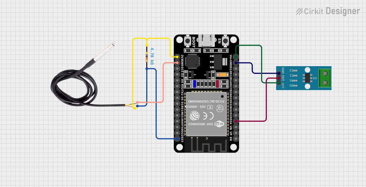
Circuit Documentation
Summary of the Circuit
This circuit integrates an ESP32 microcontroller with an ACS712 current sensor and a DS18B20 temperature sensor. The ESP32 is used as the central processing unit, capable of reading current measurements from the ACS712 and temperature readings from the DS18B20. A resistor is included in the circuit, likely for providing bias or pull-up functionality for the DS18B20 sensor.
Component List
ESP32 (30 pin)
- Description: A microcontroller with Wi-Fi and Bluetooth capabilities, featuring a wide range of GPIO pins.
- Purpose: Acts as the central processing unit for the circuit, interfacing with sensors and possibly providing connectivity.
ACS712 Current Sensor (5A, 20A, 30A)
- Description: A hall-effect-based linear current sensor capable of measuring both AC and DC currents.
- Purpose: Measures the current flowing through a point in the circuit and provides an analog voltage output proportional to the current.
DS18B20
- Description: A digital temperature sensor that provides 9-bit to 12-bit Celsius temperature measurements.
- Purpose: Measures the temperature and sends the data to the microcontroller.
Resistor (4.7k Ohms)
- Description: A passive two-terminal electrical component that implements electrical resistance as a circuit element.
- Purpose: Typically used as a pull-up resistor for the DS18B20 data line.
Wiring Details
ESP32 (30 pin)
- D34: Connected to the ACS712 Current Sensor's OUT pin.
- GND: Common ground shared with the ACS712 Current Sensor and DS18B20.
- Vin: Connected to the ACS712 Current Sensor's VCC pin.
- D23: Connected to one end of the Resistor, which is also connected to the DS18B20's signal pin.
- 3V3: Connected to the other end of the Resistor, which is also connected to the DS18B20's VCC pin.
ACS712 Current Sensor
- OUT: Connected to ESP32's D34 pin.
- GND: Connected to ESP32's GND pin.
- VCC: Connected to ESP32's Vin pin.
DS18B20
- Signal: Connected to ESP32's D23 pin through a Resistor.
- GND: Connected to ESP32's GND pin.
- VCC: Connected to ESP32's 3V3 pin through a Resistor.
Resistor (4.7k Ohms)
- Pin1: Connected to ESP32's 3V3 pin and DS18B20's VCC pin.
- Pin2: Connected to ESP32's D23 pin and DS18B20's signal pin.
Documented Code
No code was provided for the microcontroller. Typically, the code would initialize the sensors, read values from them, and perform any necessary data processing or communication tasks. Since no code is available, it is recommended to develop firmware that includes the following:
- Initialization of the ESP32's peripherals and GPIOs.
- Configuration of the ADC for reading the analog output from the ACS712.
- OneWire and/or DallasTemperature library setup for interfacing with the DS18B20.
- Main loop to periodically read current from ACS712 and temperature from DS18B20.
- Logic for any desired data output, such as serial logging, display output, or wireless transmission.
Please provide the code for the microcontroller to include it in the documentation.