Arduino UNO Based RFID Access Control with I2C LCD Feedback and Keypad Input
Circuit Documentation
Summary
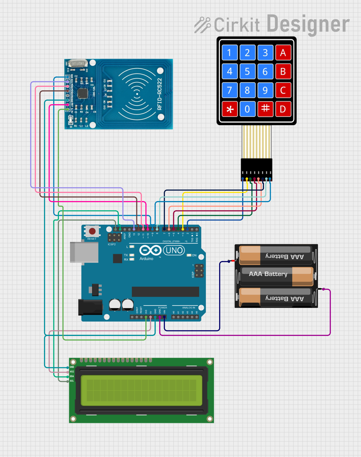
This circuit integrates an Arduino UNO with an I2C LCD 16x2 Screen, an RFID-RC522 module, a 3xAA Battery pack, and a 4x4 Membrane Matrix Keypad. The Arduino UNO serves as the central microcontroller, interfacing with the LCD for display purposes, the RFID module for scanning RFID tags, and the keypad for user input. The battery pack provides power to the Arduino, which in turn powers the RFID module and the LCD screen. Communication between the Arduino and the LCD is facilitated via the I2C protocol, while the RFID module is connected through SPI and additional GPIO pins. The keypad is interfaced using multiple digital I/O pins on the Arduino.
Component List
Arduino UNO
- Microcontroller board based on the ATmega328P
- Features digital I/O pins, analog input pins, and various power pins
- Utilized for controlling the overall functionality of the circuit
I2C LCD 16x2 Screen
- Alphanumeric liquid crystal display with 16 characters by 2 lines
- Communicates with the Arduino via the I2C protocol
- Used for displaying information to the user
RFID-RC522
- RFID reader/writer module operating at 13.56 MHz
- Interfaces with the Arduino through SPI for tag reading and writing
- Employed for identification and authentication purposes
3xAA Battery
- Power source consisting of three AA batteries in series
- Provides power to the Arduino and subsequently to other components
4x4 Membrane Matrix Keypad
- Input device with 16 buttons arranged in a 4x4 grid
- Connected to the Arduino through digital pins for user input
Wiring Details
Arduino UNO
3.3Vto RFID-RC522VCC (3.3V)5Vto I2C LCDVCC (5V)GNDto RFID-RC522GND, I2C LCDGND, and 3xAA BatteryGNDVinto 3xAA BatteryVCCSCLto I2C LCDSCLSDAto I2C LCDSDAD13to RFID-RC522SCKD12to RFID-RC522MISOD11to RFID-RC522MOSID10to RFID-RC522RSTD9to RFID-RC522SDAand KeypadC4D8to KeypadC3D7to KeypadC2D6to KeypadC1D5to KeypadR4D4to KeypadR3D3to KeypadR2D2to KeypadR1
I2C LCD 16x2 Screen
SCLto Arduino UNOSCLSDAto Arduino UNOSDAVCC (5V)to Arduino UNO5VGNDto Arduino UNOGND
RFID-RC522
VCC (3.3V)to Arduino UNO3.3VRSTto Arduino UNOD10GNDto Arduino UNOGNDIRQ(Not connected)MISOto Arduino UNOD12MOSIto Arduino UNOD11SCKto Arduino UNOD13SDAto Arduino UNOD9
3xAA Battery
VCCto Arduino UNOVinGNDto Arduino UNOGND
4X4 Membrane Matrix Keypad
R1to Arduino UNOD2R2to Arduino UNOD3R3to Arduino UNOD4R4to Arduino UNOD5C1to Arduino UNOD6C2to Arduino UNOD7C3to Arduino UNOD8C4to Arduino UNOD9
Documented Code
Arduino UNO Code (sketch.ino)
#include <Key.h>
#include <Keypad.h>

void setup() {
  // Initialization code here
}

void loop() {
  // Main code here
}
I2C LCD 16x2 Screen Code
The I2C LCD screen is controlled by the Arduino UNO via the I2C protocol. The specific initialization and control code for the LCD is not provided in the input but would typically involve setting up the I2C communication and sending commands to control the display.
RFID-RC522 Code
The RFID-RC522 module is interfaced with the Arduino UNO using SPI. The provided code does not include specific commands for the RFID operations, but the setup would involve initializing the SPI interface and implementing the protocol for reading and writing RFID tags.
3xAA Battery Code
The battery pack does not require code as it is a power source.
4X4 Membrane Matrix Keypad Code
The keypad is interfaced with the Arduino UNO using digital I/O pins. The provided code does not include specific routines for detecting key presses, but typically a matrix scanning algorithm would be implemented to determine which key is pressed.
(Note: The provided code snippets are placeholders and do not represent the complete functionality required to operate the components. Additional code would be needed to fully utilize the capabilities of each component in the circuit.)