
Arduino UNO RFID Access Control System with LED Indicators and I2C LCD Display
View and Edit Project In Cirkit Designer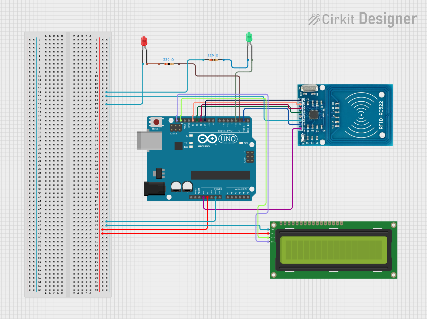
Circuit Documentation
Summary
This circuit is an RFID-based access control system using an Arduino UNO. It includes an RFID reader, two LEDs (red and green) to indicate access status, a 16x2 I2C LCD for displaying messages, and resistors for current limiting. The system reads RFID tags and grants or denies access based on a predefined authorized UID.
Component List
Arduino UNO
- Description: A microcontroller board based on the ATmega328P.
- Pins: UNUSED, IOREF, Reset, 3.3V, 5V, GND, Vin, A0, A1, A2, A3, A4, A5, SCL, SDA, AREF, D13, D12, D11, D10, D9, D8, D7, D6, D5, D4, D3, D2, D1, D0
LED: Two Pin (red)
- Description: A red LED with two pins (cathode and anode).
- Pins: cathode, anode
LED: Two Pin (green)
- Description: A green LED with two pins (cathode and anode).
- Pins: cathode, anode
RFID-RC522
- Description: An RFID reader module.
- Pins: VCC (3.3V), RST, GND, IRQ, MISO, MOSI, SCK, SDA
Resistor (220 Ohms)
- Description: A resistor with a resistance of 220 Ohms.
- Pins: pin1, pin2
16x2 I2C LCD
- Description: A 16x2 character LCD with I2C interface.
- Pins: GND, VCC, SDA, SCL
Wiring Details
Arduino UNO
- GND: Connected to the GND pins of the red LED, green LED, RFID-RC522, and 16x2 I2C LCD.
- 5V: Connected to the VCC pin of the 16x2 I2C LCD.
- 3.3V: Connected to the VCC (3.3V) pin of the RFID-RC522.
- SCL: Connected to the SCL pin of the 16x2 I2C LCD.
- SDA: Connected to the SDA pin of the 16x2 I2C LCD.
- D13: Connected to the SCK pin of the RFID-RC522.
- D12: Connected to the MISO pin of the RFID-RC522.
- D11: Connected to the MOSI pin of the RFID-RC522.
- D10: Connected to the SDA pin of the RFID-RC522.
- D3: Connected to the anode of the green LED.
- D2: Connected to pin2 of a 220 Ohm resistor.
- D1: Connected to the RST pin of the RFID-RC522.
LED: Two Pin (red)
- cathode: Connected to GND.
- anode: Connected to pin1 of a 220 Ohm resistor.
LED: Two Pin (green)
- cathode: Connected to pin2 of a 220 Ohm resistor.
- anode: Connected to D3 of the Arduino UNO.
RFID-RC522
- VCC (3.3V): Connected to 3.3V of the Arduino UNO.
- RST: Connected to D1 of the Arduino UNO.
- GND: Connected to GND.
- SCK: Connected to D13 of the Arduino UNO.
- MISO: Connected to D12 of the Arduino UNO.
- MOSI: Connected to D11 of the Arduino UNO.
- SDA: Connected to D10 of the Arduino UNO.
Resistor (220 Ohms)
- pin1: Connected to the anode of the red LED.
- pin2: Connected to D2 of the Arduino UNO.
16x2 I2C LCD
- GND: Connected to GND.
- VCC: Connected to 5V of the Arduino UNO.
- SDA: Connected to SDA of the Arduino UNO.
- SCL: Connected to SCL of the Arduino UNO.
Code Documentation
#include <SPI.h>
#include <MFRC522.h>
#include <Wire.h>
#include <LiquidCrystal_I2C.h>

#define SS_PIN 10  // Pin for SS (Slave Select)
#define RST_PIN 1  // Pin for Reset
#define RED_LED_PIN 2
#define GREEN_LED_PIN 3

// Initialize MFRC522 RFID reader
MFRC522 mfrc522(SS_PIN, RST_PIN);

// Initialize the LCD with I2C address 0x27 and a 16x2 display
LiquidCrystal_I2C lcd(0x27, 16, 2);

// Predefined authorized RFID tag UID (you can replace this with your own UID)
byte authorizedUID[4] = {0xDE, 0xAD, 0xBE, 0xEF};  // Example authorized UID

void setup() {
  Serial.begin(9600);  // Start the serial communication
  SPI.begin();         // Start SPI bus for RFID module
  mfrc522.PCD_Init();  // Initialize the MFRC522 RFID module
  lcd.begin(16, 2);    // Initialize LCD (16x2)
  lcd.backlight();     // Turn on the backlight

  pinMode(RED_LED_PIN, OUTPUT);
  pinMode(GREEN_LED_PIN, OUTPUT);

  // Display "TUP_QUEZON" for 2 seconds
  lcd.setCursor(0, 0);
  lcd.print("TUP_QUEZON");
  delay(2000);
  lcd.clear();
}

void loop() {
  // Display "Scan your Card" message
  lcd.setCursor(0, 0);
  lcd.print("Scan your Card");

  // Check if a new RFID card is present
  if (!mfrc522.PICC_IsNewCardPresent()) {
    return;  // No card detected, continue checking
  }

  if (!mfrc522.PICC_ReadCardSerial()) {
    return;  // Failed to read card serial
  }

  // If we reach here, an RFID card has been detected and read
  Serial.println("Card detected!");

  // Display the UID of the scanned card for debugging
  Serial.print("ID Number: ");
  for (byte i = 0; i < mfrc522.uid.size; i++) {
    Serial.print(mfrc522.uid.uidByte[i], HEX);
  }
  Serial.println();

  // Check if the scanned card matches the authorized UID
  bool isAuthorized = true;
  for (byte i = 0; i < 4; i++) {
    if (mfrc522.uid.uidByte[i] != authorizedUID[i]) {
      isAuthorized = false;  // Card does not match the authorized UID
      break;
    }
  }

  if (isAuthorized) {
    // Access Granted
    lcd.clear();
    lcd.setCursor(0, 0);
    lcd.print("Access Granted");
    digitalWrite(GREEN_LED_PIN, HIGH);  // Turn on the green LED
    digitalWrite(RED_LED_PIN, LOW);    // Ensure the red LED is off
  } else {
    // Access Denied
    lcd.clear();
    lcd.setCursor(0, 0);
    lcd.print("Access Denied");
    digitalWrite(RED_LED_PIN, HIGH);   // Turn on the red LED
    digitalWrite(GREEN_LED_PIN, LOW);  // Ensure the green LED is off
  }

  delay(1000);  // Wait for 1 second
  lcd.clear();  // Clear the LCD screen
}
This code initializes the RFID reader and the LCD, sets up the pins for the LEDs, and continuously checks for RFID cards. When a card is detected, it compares the card's UID with a predefined authorized UID and grants or denies access accordingly, displaying the result on the LCD and lighting up the appropriate LED.