Cirkit Designer
Your all-in-one circuit design IDE
Home /
Project Documentation
Wi-Fi Controlled Servo with Real-Time Clock using ESP32 and DS3231
Circuit Documentation
Summary
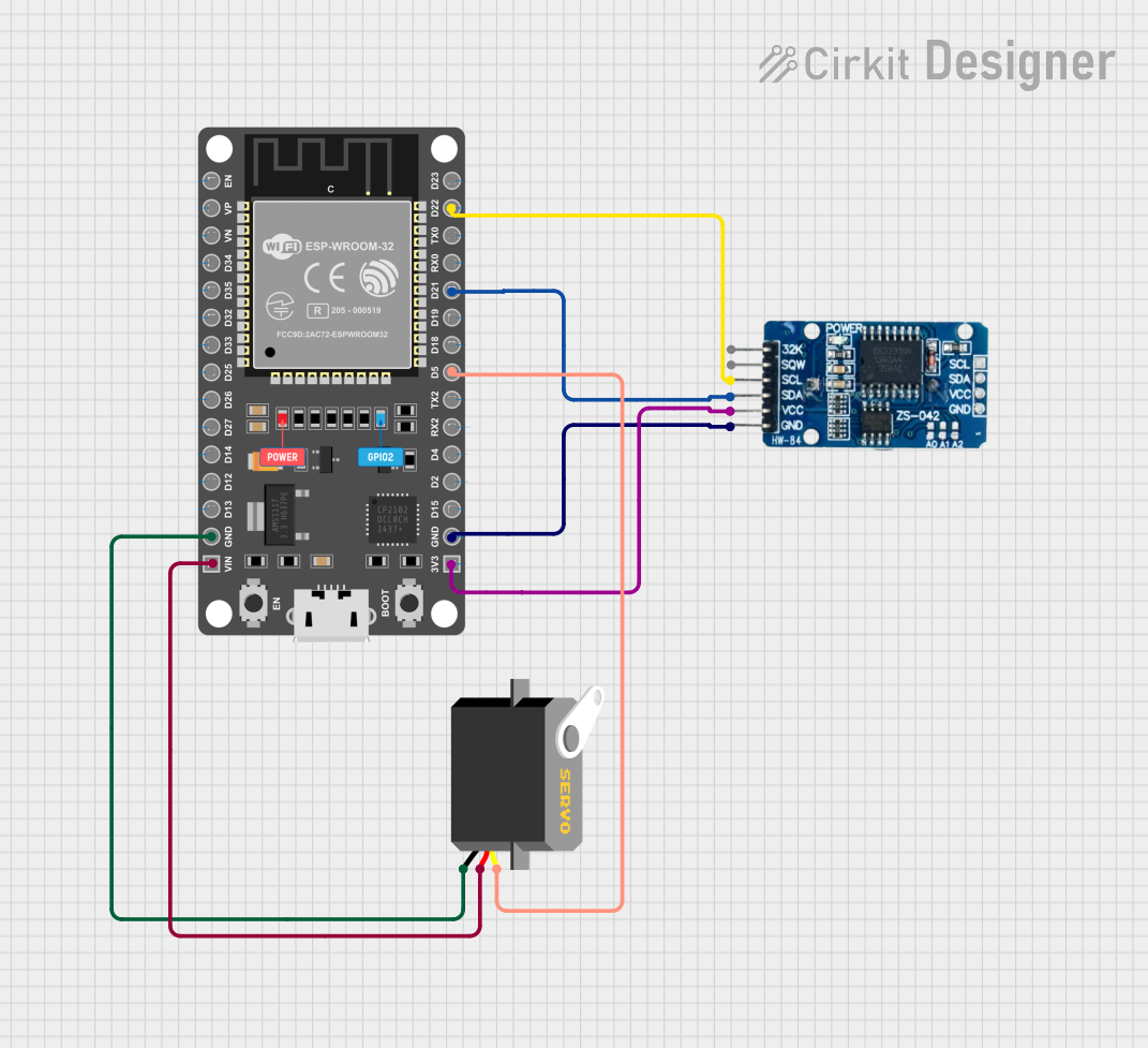
This document provides a detailed overview of a circuit that includes an ESP32 microcontroller, a Servo motor, and an RTC DS3231 module. The ESP32 serves as the central controller, interfacing with the Servo motor and the RTC module to perform various tasks. The Servo motor is controlled via a pulse signal from the ESP32, while the RTC module provides accurate timekeeping.
Component List
ESP32 DEVKIT V1 (30 pins)
- Description: A powerful microcontroller with built-in Wi-Fi and Bluetooth capabilities.
- Pins: EN, VP, VN, D34, D35, D32, D33, D25, D26, D27, D14, D12, D13, GND, VIN, 3V3, D15, D2, D4, RX2, TX2, D5, D18, D19, D21, RX0, TX0, D22, D23
Servo
- Description: A motor that can be precisely controlled to rotate to a specific angle.
- Pins: gnd, vcc, pulse
RTC DS3231
- Description: A real-time clock module that provides accurate timekeeping.
- Pins: 32K, SQW, SCL, SDA, VCC, GND
Wiring Details
ESP32 DEVKIT V1 (30 pins)
- GND is connected to Servo gnd and RTC DS3231 GND
- VIN is connected to Servo vcc
- 3V3 is connected to RTC DS3231 VCC
- D5 is connected to Servo pulse
- D21 is connected to RTC DS3231 SDA
- D22 is connected to RTC DS3231 SCL
Servo
- gnd is connected to ESP32 GND
- vcc is connected to ESP32 VIN
- pulse is connected to ESP32 D5
RTC DS3231
- GND is connected to ESP32 GND
- VCC is connected to ESP32 3V3
- SDA is connected to ESP32 D21
- SCL is connected to ESP32 D22
Code
No code is provided for this circuit.
This document provides a comprehensive overview of the circuit, including a summary, detailed component list, wiring details, and code documentation. This should serve as a useful reference for understanding and replicating the circuit.