
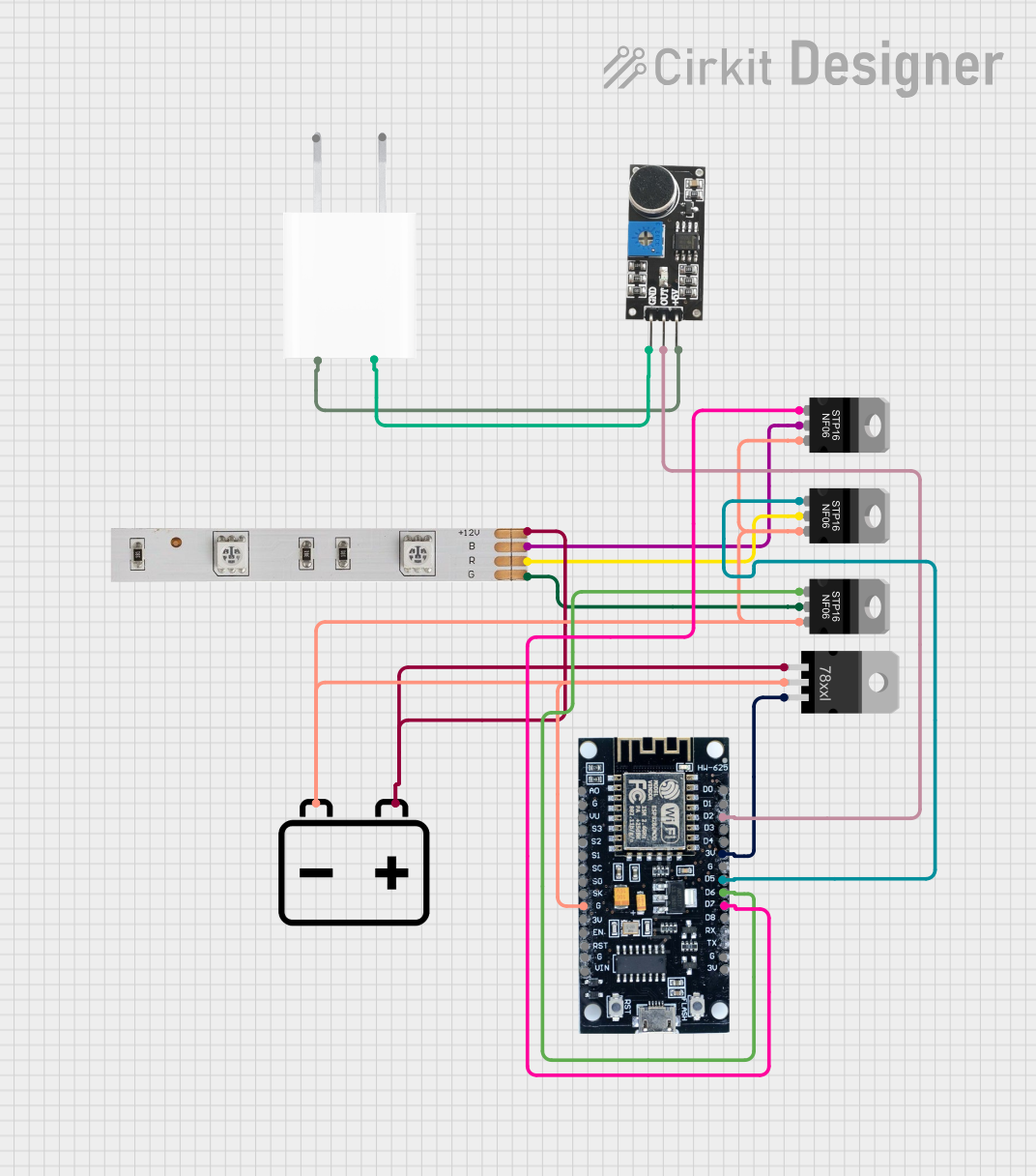
Circuit Documentation
Summary
This circuit is a sound-reactive RGB LED strip light system. It uses an ESP8266 microcontroller to read the output from a sound sensor and control an RGB LED strip via MOSFETs. The system is powered by a 12V battery, with a voltage regulator providing the necessary 3V for the ESP8266. A 5V adapter powers the sound sensor.
Component List
ESP8266
- Description: A Wi-Fi enabled microcontroller.
- Pins: 3V, G, D8, D7, D6, D5, D4, D3, D2, D1, D0, A0, S3, S2, S1, SC, S0, SK, EN, VIN, RST, VU
12V Battery
- Description: Provides 12V power to the circuit.
- Pins: -, +
LED Strip
- Description: RGB LED strip.
- Pins: B, +12V, R, G
Sound Sensor
- Description: Detects sound levels.
- Pins: 5V +, OUT, GND
STP16NF06 N-Channel Power MOSFET
- Description: Used to control the RGB LED strip.
- Pins: gate, drain, source
Voltage Regulator
- Description: Regulates 12V to 3V for the ESP8266.
- Pins: IN, GND, OUT
5V Adapter
- Description: Provides 5V power to the sound sensor.
- Pins: AC In 1, AC In 2, 5V, GND
Wiring Details
ESP8266
- 3V: Connected to OUT of the Voltage Regulator.
- G: Connected to the common ground (GND).
- D7: Connected to the gate of the MOSFET controlling the blue LED.
- D6: Connected to the gate of the MOSFET controlling the green LED.
- D5: Connected to the gate of the MOSFET controlling the red LED.
- D2: Connected to the OUT pin of the Sound Sensor.
12V Battery
- -: Connected to the source of all MOSFETs and the GND of the Voltage Regulator and ESP8266.
- +: Connected to the +12V pin of the LED Strip and the IN pin of the Voltage Regulator.
LED Strip
- B: Connected to the drain of the MOSFET controlling the blue LED.
- +12V: Connected to the + pin of the 12V Battery.
- R: Connected to the drain of the MOSFET controlling the red LED.
- G: Connected to the drain of the MOSFET controlling the green LED.
Sound Sensor
- 5V +: Connected to the 5V pin of the 5V Adapter.
- OUT: Connected to D2 of the ESP8266.
- GND: Connected to the GND pin of the 5V Adapter.
STP16NF06 N-Channel Power MOSFET
- Gate:
- One MOSFET gate connected to D7 of the ESP8266.
- One MOSFET gate connected to D6 of the ESP8266.
- One MOSFET gate connected to D5 of the ESP8266.
- Drain:
- One MOSFET drain connected to B of the LED Strip.
- One MOSFET drain connected to R of the LED Strip.
- One MOSFET drain connected to G of the LED Strip.
- Source: Connected to the - pin of the 12V Battery.
Voltage Regulator
- IN: Connected to the + pin of the 12V Battery.
- GND: Connected to the common ground (GND).
- OUT: Connected to the 3V pin of the ESP8266.
5V Adapter
- 5V: Connected to the 5V + pin of the Sound Sensor.
- GND: Connected to the GND pin of the Sound Sensor.
Code Documentation
/*
 * Sound Reactive RGB LED Strip Light
 * This code reads the output from a sound sensor and controls an RGB LED strip
 * using MOSFETs connected to the ESP8266 microcontroller.
 */

const int soundSensorPin = D2; // Sound sensor output pin
const int redLEDPin = D5;      // MOSFET gate for red LED
const int greenLEDPin = D6;    // MOSFET gate for green LED
const int blueLEDPin = D7;     // MOSFET gate for blue LED

void setup() {
  pinMode(soundSensorPin, INPUT);
  pinMode(redLEDPin, OUTPUT);
  pinMode(greenLEDPin, OUTPUT);
  pinMode(blueLEDPin, OUTPUT);
}

void loop() {
  int soundLevel = analogRead(soundSensorPin);
  int brightness = map(soundLevel, 0, 1023, 0, 255);

  analogWrite(redLEDPin, brightness);
  analogWrite(greenLEDPin, brightness);
  analogWrite(blueLEDPin, brightness);

  delay(10); // Small delay to smooth out the response
}
This code initializes the pins for the sound sensor and the MOSFET gates controlling the RGB LED strip. In the loop function, it reads the sound level from the sound sensor, maps the sound level to a brightness value, and writes this brightness value to the MOSFET gates, thereby controlling the brightness of the RGB LEDs based on the sound level.