
Arduino-Controlled Line-Following Robot with Obstacle Detection
View and Edit Project In Cirkit Designer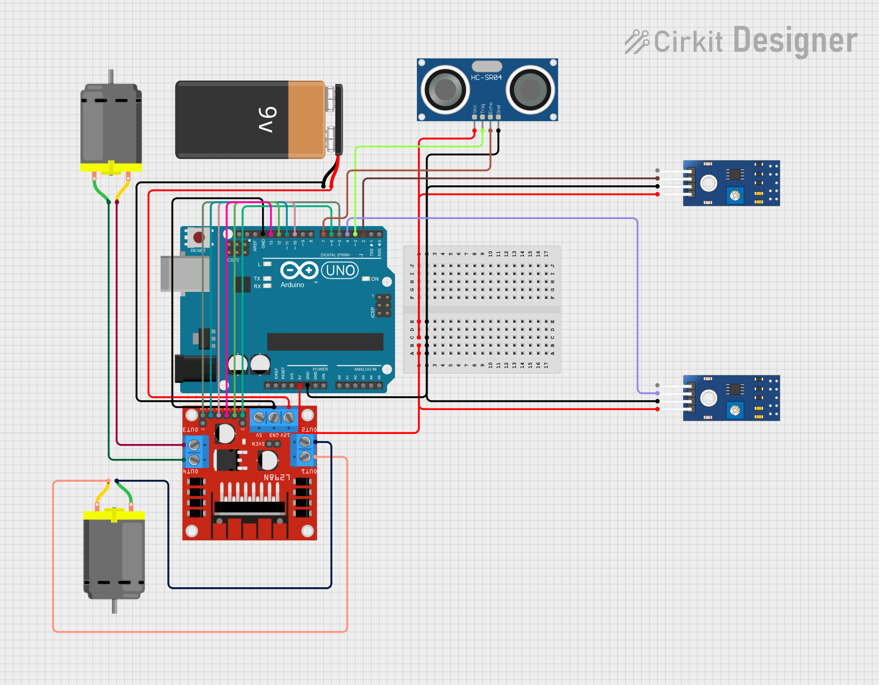
Circuit Documentation
Summary
This circuit is designed to control a pair of DC motors using an Arduino UNO microcontroller and an L298N DC motor driver. It includes sensors for detecting lines (TCRT 5000 IR sensors) and measuring distance (HC-SR04 Ultrasonic Sensor). The circuit is powered by a 9V battery, which supplies power to the motor driver and, through the Arduino, to the sensors. The Arduino UNO is programmed to read sensor inputs and control the speed and direction of the motors accordingly.
Component List
Arduino UNO
- Microcontroller board based on the ATmega328P
- It has 14 digital input/output pins, 6 analog inputs, a 16 MHz quartz crystal, a USB connection, a power jack, an ICSP header, and a reset button.
L298N DC Motor Driver
- A dual H-bridge motor driver that can drive two DC motors or one stepper motor.
- It has pins for motor power supply, ground, control inputs, and motor outputs.
9V Battery
- Provides the power supply for the motor driver and indirectly for the other components through the Arduino.
DC Motor (x2)
- Converts electrical energy into mechanical energy to drive the wheels of a robot or a similar device.
TCRT 5000 IR Sensor (x2)
- An infrared sensor that can detect the presence of an object or changes in a surface, typically used for line tracking.
HC-SR04 Ultrasonic Sensor
- Measures distances by emitting ultrasonic waves and measuring the time it takes for the echo to return.
Wiring Details
Arduino UNO
5VandGNDpins are used to supply power to the HC-SR04 Ultrasonic Sensor and both TCRT 5000 IR Sensors.- Digital pins
D2toD13are used to interface with the L298N motor driver and sensors.
L298N DC Motor Driver
12VandGNDare connected to the 9V battery.IN1,IN2,IN3, andIN4are connected to Arduino digital pinsD13,D12,D11, andD10respectively for motor control.ENAandENBare connected to Arduino digital pinsD6andD5for speed control.OUT1,OUT2,OUT3, andOUT4are connected to the DC motors.
9V Battery
+is connected to the12Vinput of the L298N motor driver.-is connected to theGNDpin of the L298N motor driver and Arduino GND.
DC Motors
- Each motor has two pins connected to two output pins on the L298N motor driver.
TCRT 5000 IR Sensors
VCCpins are connected to the Arduino5V.GNDpins are connected to the ArduinoGND.DOpins are connected to Arduino digital pinsD2andD4for digital output.
HC-SR04 Ultrasonic Sensor
VCCis connected to the Arduino5V.GNDis connected to the ArduinoGND.TRIGandECHOpins are connected to Arduino digital pinsD3andD7respectively.
Documented Code
// Definición pines EnA y EnB para el control de la velocidad
int VelocidadMotor1 = 6;
int VelocidadMotor2 = 5;

// Definición de los pines de control de giro de los motores In1, In2, In3 e In4
int Motor1A = 13;
int Motor1B = 12;
int Motor2C = 11;
int Motor2D = 10;

// Sensores infrarrojo - izquierdo y derecho
int infraPin  = 2;
int infraPin1 = 4;

// Variables para la captura de los valores: 0 - fondo claro y 1 - línea negra
int valorInfra = 0;
int valorInfra1 = 0;

// Configuración inicial
void setup() {
  Serial.begin(9600);

  delay(1000);

  // Establecemos modo de los pines de los sensores infrarrojo
  pinMode(infraPin, INPUT);
  pinMode(infraPin1, INPUT);

  // Establecemos modo de los pines del control de motores
  pinMode(Motor1A,OUTPUT);
  pinMode(Motor1B,OUTPUT);
  pinMode(Motor2C,OUTPUT);
  pinMode(Motor2D,OUTPUT);
  pinMode(VelocidadMotor1, OUTPUT);
  pinMode(VelocidadMotor2, OUTPUT);

  // Configuramos los dos motores a velocidad 150/255
  analogWrite(VelocidadMotor1, 150);
  analogWrite(VelocidadMotor2, 150);

  // Configuramos sentido de giro
  digitalWrite(Motor1A, LOW);
  digitalWrite(Motor1B, LOW);
  digitalWrite(Motor2C, LOW);
  digitalWrite(Motor2D, LOW);
}

// Ejecución contínua
void loop() {
  // Leemos el valor de los infrarrojo: 0 - fondo claro y 1 - línea negra
  valorInfra = digitalRead(infraPin);
  valorInfra1 = digitalRead(infraPin1);

  Serial.println(valorInfra);
  Serial.println(valorInfra1);

  // Cuatro escenarios: De frente
  if(valorInfra == 0 && valorInfra1 == 0){
    Serial.println("Ninguno en linea");

    // Modificamos sentido de giro de los motores
    digitalWrite(Motor1A, HIGH);
    digitalWrite(Motor2D, HIGH);
    delay(20);
    digitalWrite(Motor1A, LOW);
    digitalWrite(Motor2D,LOW);
    delay(20);
  }

  // El robot encuentra línea negra con el infrarrojo derecho y hay que corregir girando a la derecha
  if(valorInfra == 0 && valorInfra1 == 1){
    Serial.println("Derecho en linea");

    // Modificamos sentido de giro de los motores
    digitalWrite(Motor1A, LOW);
    digitalWrite(Motor2D,LOW);
    delay(25);
    digitalWrite(Motor1A, HIGH);
    digitalWrite(Motor2D,LOW);
    delay(20);
  }

  // El robot encuentra línea negra con el infrarrojo izquierdo y hay que corregir girando a la izquierda
  if(valorInfra == 1 && valorInfra1 == 0){
    Serial.println("Izquierdo en linea");

    // Modificamos sentido de giro de los motores
    digitalWrite(Motor1A,LOW);
    digitalWrite(Motor2D, LOW);
    delay(25);
    digitalWrite(Motor1A,LOW);
    digitalWrite(Motor2D, HIGH);
    delay(20);
  }

  // Los dos sensores infrarrojos encuentran una línea negra, el final del circuito
  if(valorInfra == 1 && valorInfra1 == 1){
    Serial.println("Ambos en linea");

    // Paramos los motores
    digitalWrite(Motor1A, LOW);
    digitalWrite(Motor1B, LOW);
    digitalWrite(Motor2C, LOW);
    digitalWrite(Motor2D, LOW);
  }
}
This code is designed to be uploaded to the Arduino UNO microcontroller. It initializes the motor control and sensor input pins, sets a default motor speed, and then continuously reads the IR sensor values to determine the robot's path. Depending on the sensor readings, it adjusts the motor control signals to steer the robot accordingly.