
ESP32-Based GPS Tracker with SD Card Logging and Barometric Sensor
View and Edit Project In Cirkit Designer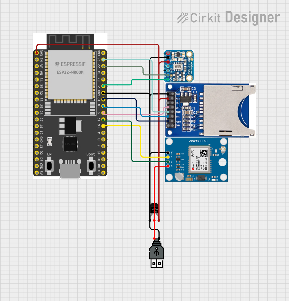
Circuit Documentation
Summary
The circuit in question is designed to interface an ESP32 Wroom Dev Kit with several peripheral devices, including a Neo 6M GPS Module, a voltage regulator, a USB power source, an MPL3115A2 pressure sensor, and an SD card reader. The ESP32 serves as the central microcontroller, managing data communication between the GPS module, the pressure sensor, and the SD card reader. The voltage regulator is used to step down the voltage from the USB power source to a level suitable for the ESP32 and other 3.3V components. The GPS module provides location data, the MPL3115A2 sensor measures atmospheric pressure, and the SD card reader is used for data logging purposes.
Component List
ESP 32 Wroom Dev Kit
- Description: A development board based on the ESP32 microcontroller, featuring Wi-Fi and Bluetooth connectivity, along with a variety of GPIO pins for interfacing with other components.
- Pins: 3V3, EN, VP, VN, GPIO 34, GPIO 35, GPIO 32, GPIO 33, GPIO 25, GPIO 26, GPIO 27, GPIO 14, GND, GPIO 13, SD2, SD3, CMD, V5, GPIO 23, GPIO 22, TXD, RXD, GPIO 21, GPIO 19, GPIO 18, GPIO 5, GPIO 17, GPIO 16, GPIO 4, GPIO 0, GPIO 2, GPIO 15, SD1, SD0, CLK
Neo 6M GPS Module
- Description: A compact GPS module that provides accurate geographical location data.
- Pins: GND, TX, RX, VCC
Voltage Regulator
- Description: A device that maintains a constant voltage level to the output load.
- Pins: GND, IN, OUT
USB Power
- Description: A power source that provides power through a USB interface.
- Pins: +, -
MPL3115A2
- Description: A high-precision pressure sensor with I2C interface.
- Pins: Vin, GND, 3.3V, INT2, INT1, SCL, SDA
SD Card Reader (2 Pins)
- Description: A device that allows reading from and writing to SD cards.
- Pins: GND, 3.3V, 5V, CS, MOSI, SCK, MISO
Wiring Details
ESP 32 Wroom Dev Kit
- 3V3: Connected to the 3.3V output from the Voltage Regulator, MPL3115A2, and SD Card Reader.
- GND: Common ground with Voltage Regulator, USB Power, Neo 6M GPS Module, MPL3115A2, and SD Card Reader.
- GPIO 23: Connected to the MOSI pin of the SD Card Reader.
- GPIO 22: Connected to the SCL pin of the MPL3115A2.
- GPIO 21: Connected to the SDA pin of the MPL3115A2.
- GPIO 19: Connected to the MISO pin of the SD Card Reader.
- GPIO 18: Connected to the SCK pin of the SD Card Reader.
- GPIO 5: Connected to the CS pin of the SD Card Reader.
- GPIO 17: Connected to the RX pin of the Neo 6M GPS Module.
- GPIO 16: Connected to the TX pin of the Neo 6M GPS Module.
Neo 6M GPS Module
- GND: Common ground with other components.
- TX: Connected to GPIO 16 of the ESP 32 Wroom Dev Kit.
- RX: Connected to GPIO 17 of the ESP 32 Wroom Dev Kit.
- VCC: Connected to the output of the Voltage Regulator.
Voltage Regulator
- GND: Common ground with other components.
- IN: Connected to the + pin of the USB Power.
- OUT: Connected to the 3.3V power rail supplying the ESP 32 Wroom Dev Kit, MPL3115A2, and SD Card Reader.
USB Power
- +: Connected to the IN pin of the Voltage Regulator.
- -: Common ground with other components.
MPL3115A2
- Vin: Not connected in the provided net list.
- GND: Common ground with other components.
- 3.3V: Connected to the 3.3V power rail from the Voltage Regulator.
- INT2: Not connected in the provided net list.
- INT1: Not connected in the provided net list.
- SCL: Connected to GPIO 22 of the ESP 32 Wroom Dev Kit.
- SDA: Connected to GPIO 21 of the ESP 32 Wroom Dev Kit.
SD Card Reader (2 Pins)
- GND: Common ground with other components.
- 3.3V: Connected to the 3.3V power rail from the Voltage Regulator.
- 5V: Not connected in the provided net list.
- CS: Connected to GPIO 5 of the ESP 32 Wroom Dev Kit.
- MOSI: Connected to GPIO 23 of the ESP 32 Wroom Dev Kit.
- SCK: Connected to GPIO 18 of the ESP 32 Wroom Dev Kit.
- MISO: Connected to GPIO 19 of the ESP 32 Wroom Dev Kit.
Documented Code
No code was provided for the microcontrollers in the circuit. Therefore, this section is not applicable for the current documentation. When code becomes available, it should be documented here with appropriate comments and explanations for each function and routine.