Cirkit Designer
Your all-in-one circuit design IDE
Home /
Project Documentation
Bluetooth-Controlled Robotic Car with L298N Motor Driver and Arduino UNO
Circuit Documentation
Summary of the Circuit
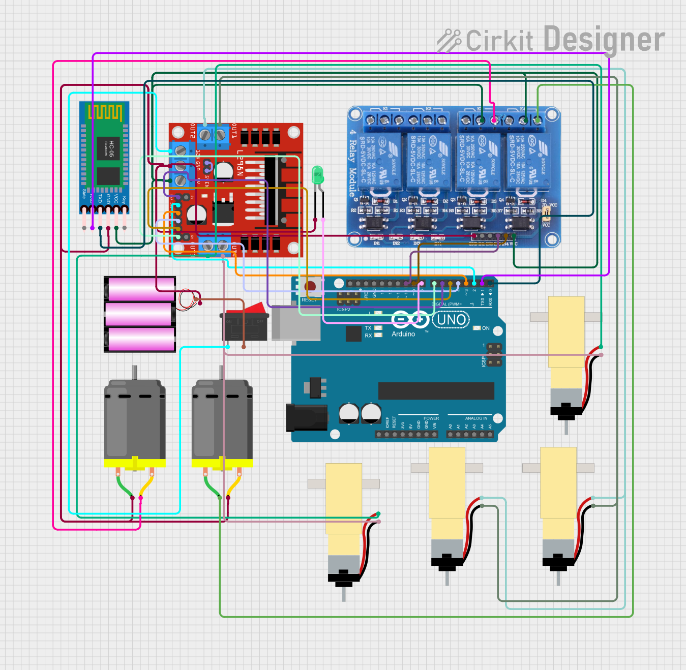
This circuit is designed to control a set of DC motors using an L298N motor driver, which is interfaced with an Arduino UNO microcontroller. The Arduino UNO receives commands via a Bluetooth connection through the HC-05 Bluetooth Module to drive the motors in various directions (forward, backward, left, right) and to stop them. The circuit also includes a relay module to control additional DC motors, a battery to provide power, an LED indicator, and a rocker switch to control the power supply.
Component List
L298N DC Motor Driver
- Description: A motor driver module capable of driving two DC motors.
- Pins: OUT1, OUT2, 12V, GND, 5V, OUT3, OUT4, 5V-ENA-JMP-I, 5V-ENA-JMP-O, +5V-J1, +5V-J2, ENA, IN1, IN2, IN3, IN4, ENB
Hobby Gearmotor with 48:1 Gearbox
- Description: A DC gearmotor used for providing mechanical motion.
- Pins: pin 1, pin 2
Battery 12V
- Description: A 12V battery used as the power source for the circuit.
- Pins: +, -
Relay 4 Channel 5V
- Description: A 4-channel relay module for controlling high power devices.
- Pins: GND, IN1, IN2, IN3, IN4, VCC, COM1, COM2, COM3, COM4, NO1, NO2, NO3, NO4, NC1, NC2, NC3, NC4
DC Motor
- Description: A standard DC motor for rotational motion.
- Pins: pin 1, pin 2
LED: Two Pin (Green)
- Description: A green LED used as an indicator.
- Pins: cathode, anode
Rocker Switch
- Description: A switch to control the power supply to the circuit.
- Pins: 1, 2
Arduino UNO
- Description: A microcontroller board based on the ATmega328P.
- Pins: UNUSED, IOREF, Reset, 3.3V, 5V, GND, Vin, A0, A1, A2, A3, A4, A5, SCL, SDA, AREF, D13, D12, D11, D10, D9, D8, D7, D6, D5, D4, D3, D2, D1, D0
HC-05 Bluetooth Module
- Description: A Bluetooth module for wireless communication.
- Pins: Key, VCC, TXD, RXD, State, GND
Wiring Details
L298N DC Motor Driver
- OUT1, OUT2: Connected to the first pair of Hobby Gearmotors.
- 12V: Connected to one terminal of the Rocker Switch.
- GND: Common ground with the battery, Bluetooth module, LED, and other DC motors.
- 5V: Powers the HC-05 Bluetooth Module and the Relay 4 Channel 5V module.
- OUT3, OUT4: Connected to the second pair of Hobby Gearmotors.
- 5V-ENA-JMP-I, 5V-ENA-JMP-O: Jumper setting for enabling the onboard 5V regulator.
- ENA, ENB: Controlled by Arduino UNO pins D6 and D7 for enabling motor driver channels.
- IN1, IN2, IN3, IN4: Controlled by Arduino UNO pins D2, D3, D4, and D5 for motor direction control.
Hobby Gearmotor with 48:1 Gearbox
- pin 1, pin 2: Connected to the corresponding OUT pins of the L298N DC Motor Driver.
Battery 12V
- +: Connected to the other terminal of the Rocker Switch.
- -: Common ground with the circuit.
Relay 4 Channel 5V
- GND: Common ground with the circuit.
- IN3, IN4: Controlled by Arduino UNO pins D10 and D9.
- VCC: Powered by the 5V output from the L298N DC Motor Driver.
- COM3, COM4: Connected to the VCC of the Relay module.
- NO3, NO4: Connected to the additional DC Motors.
DC Motor
- pin 1, pin 2: One motor is connected to the Relay module (NO3, NO4), and the other shares a common ground with the circuit.
LED: Two Pin (Green)
- cathode: Connected to the common ground.
- anode: Controlled by Arduino UNO pin D8.
Rocker Switch
- 1, 2: Switches the 12V power supply from the battery to the L298N DC Motor Driver.
Arduino UNO
- D2, D3, D4, D5, D6, D7: Control signals for the L298N DC Motor Driver.
- D8: Controls the LED indicator.
- D9, D10: Control signals for the Relay module.
- D0, D1: Serial communication with the HC-05 Bluetooth Module.
HC-05 Bluetooth Module
- VCC: Powered by the 5V output from the L298N DC Motor Driver.
- GND: Common ground with the circuit.
- TXD, RXD: Serial communication with Arduino UNO pins D0 and D1.
Documented Code
Arduino UNO Code
// Pin Definitions
#define IN1 7
#define IN2 6
#define IN3 5
#define IN4 4
#define ENA 10
#define ENB 9

char command; // Stores the received command via Bluetooth

void setup() {
  // Motor driver pins setup
  pinMode(IN1, OUTPUT);
  pinMode(IN2, OUTPUT);
  pinMode(IN3, OUTPUT);
  pinMode(IN4, OUTPUT);
  pinMode(ENA, OUTPUT);
  pinMode(ENB, OUTPUT);
  // Initialize Serial communication for Bluetooth
  Serial.begin(9600);
}

void loop() {
  // Check if there is data received via Bluetooth
  if (Serial.available() > 0) {
    command = Serial.read(); // Read the command from Bluetooth

    switch (command) {
      case 'F': // Move Forward
        moveForward();
        Serial.println("carForward");
        break;

      case 'B': // Move Backward
        moveBackward();
        Serial.println("carBACKWARD");
        break;

      case 'L': // Turn Left
        turnLeft();
        Serial.println("carLEFT");
        break;

      case 'R': // Turn Right
        turnRight();
        Serial.println("carRIGHT");
        break;

      case 'S': // Stop
        stopCar();
        break;

      default:
        stopCar(); // Stop if the command is not recognized
    }
  }
}

// Function to move the car forward
void moveForward() {
  digitalWrite(IN1, HIGH);
  digitalWrite(IN2, LOW);
  digitalWrite(IN3, HIGH);
  digitalWrite(IN4, LOW);
  analogWrite(ENA, 255); // Full speed
  analogWrite(ENB, 255); // Full speed
}

// Function to move the car backward
void moveBackward() {
  digitalWrite(IN1, LOW);
  digitalWrite(IN2, HIGH);
  digitalWrite(IN3, LOW);
  digitalWrite(IN4, HIGH);
  analogWrite(ENA, 255); // Full speed
  analogWrite(ENB, 255); // Full speed
}

// Function to turn the car left
void turnLeft() {
  digitalWrite(IN1, LOW);
  digitalWrite(IN2, HIGH);
  digitalWrite(IN3, HIGH);
  digitalWrite(IN4, LOW);
  analogWrite(ENA, 255); // Full speed
  analogWrite(ENB, 255); // Full speed
}

// Function to turn the car right
void turnRight() {
  digitalWrite(IN1, HIGH);
  digitalWrite(IN2, LOW);
  digitalWrite(IN3, LOW);
  digitalWrite(IN4, HIGH);
  analogWrite(ENA, 255); // Full speed
  analogWrite(ENB, 255); // Full speed
}

// Function to stop the car
void stopCar() {
  digitalWrite(IN1, LOW);
  digitalWrite(IN2, LOW);
  digitalWrite(IN3, LOW);
  digitalWrite(IN4, LOW);
  analogWrite(ENA, 0); // Stop
  analogWrite(ENB, 0); // Stop
}
(Note: The code for the L298N DC motor driver microcontroller instance is empty and thus not included in the documentation.)